
- Socket Communications User's Guide Cordless Serial Adapter
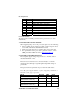


Pin Assignments
Pin # Directio
n
Function
1 IN DCD — Carrier detect
2 IN RXD serial data from local host
3 OUT TXD serial data to local host
4 OUT DTR Data terminal ready
5 Ground
6 IN DSR Data set ready
7 OUT RTS Request to send to local host
8 IN CTS Clear to send from local host
9 Optional power input (3.3 to 5.0 Vdc)
Power Mechanisms:
The CSA operates from DC power and can be powered via one of two
mechanisms:
1. From the Power Jack on the CSA.
When supplying DC power to the power jack, please note the following:
• The acceptable supply voltage for normal operation ranges from 3.5
to 5.5 VDC, with an Absolute Maximum is 5.6V.
• The Power supply must rise to its final voltage in less than 1mS.
• For specifications of the power jack’s physical connector, refer to
SMK part number LGP3131-0111 at
http://www.smk.co.jp.
2. From Pin 9 of the DB-9 Connector.
The acceptable supply voltage ranges from 3.5 to 12 VDC, with an
Absolute Maximum of 12V.
The CSA was not intended to be connected directly to a vehicle’s
electrical system, although a cigarette lighter adapter/DC charger is
permissible.
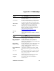
The typical current requirements are provided in the table below.
Note: The power supply should be capable of supplying a minimum of
200 mA to ensure proper operation.
Mode Average Max Units
Connected 40.5 76.5 mA
Connected standby
(RS-232 transceiver off)
3.5 53.0 mA
Waiting to connect 39.1 55.9 mA
Waiting to connect standby
(RS-232 transceiver off)
2.3 19.1 mA
APPENDIX A: SPECIFICATIONS 35