
User Manual


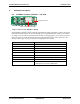
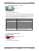
Table Of Contents
- Overview
- Hardware Description
- System Requirements
- Desktop Test Set-up
- Hardware Configuration
- WinCE Test Setup
- HCI Test Setup
- Suspend\Resume
- Bluetooth Driver List
- Certification Testing Utilities
- KwikBlue Development Board Jumpers
- Audio CODEC Setup (Optional)
- KwikBlue Development Board Bill of Materials (BOM)
- CODEC Board Bill of Materials (BOM)
- Errata
- Appendix A: BC01 vs. BC02 Pin Assignments

KwikBlue Module Development Kit Installation Guide
2. Hardware Description
2.1. KwikBlue-1 (Class 1) Module – Top View
Figure 1: Top View of the KwikBlue-1 Module
The KwikBlue-1 Module contains CSR’s BC2-EXT (BC02) chipset which has a complete transceiver
radio and baseband controller section: 16 bit RISC processor, RAM and Flash memory. Also built in
are a high- accuracy reference oscillator and a subclock for managing power to extremely low levels.
Protocol software is already downloaded into the integrated Flash memory and it interfaces to the
HCI layer of the upper layer protocol stack on an appropriate host system.
20-pin Connector
Class 1 SMD Bluetooth Module
Features Values
Carrier Module Dimensions 35.0 x 12.0 x 2.8 mm (height above PCB)
Power Level +16 dBm Max.
Program Memory 4 Mbits (256k bytes x 16 bits) Flash
RAM 32k bytes x 16 bits
Reference Oscillator Built-in
Sub Clock Oscillator Built-in
Audio Interface
PCM A-Law, µ-Law (CVSD)
Serial Data Interface UART (BCSP)
Physical Connection
Board-to-board connector:
Matsushita Electric Works AXK6F20345
Table 1: KwikBlue-2 Module Features List
April 23, 2004 Copyright © 2003-2004 Socket Communications, Inc. Page 2
Document#: 6410-00215-C CONFIDENTIAL Revision 1.04