
Datasheet


SONARANGE UPR-A 04.17 e
This Information corresponds to the current state of knowledge. SNT reserves the right to make technical changes. Do not use these products in any application
where failure of the product could result in personal injury. Liability for consequential damage resulting from the use of SNT products is excluded.
SNT Sensortechnik AG, Hammerstrasse 6, CH-8180 Bülach, Switzerland, Phone +41 44 817 29 22, Fax +41 44 817 10 83, info@sntag.ch 4/6
www.sntag.ch
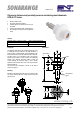
0mm
1000
mm
1500
mm
500
mm
400mm
Synchronization ("Y" option)
If several sensors are placed close together and scan the
same object or if a common background is present, the
sensors must be synchronized. For this, the Teach/Sync.
leads of all sensors (max. 6 sensors) are interconnected.
Important is the order:
1. teach each sensor individually (!)
2. turn off the power
3. interconnect all Teach/Sync. lines
4. power on again only when everything is wired!
Suppression mode ("Y" option)
This additional function is interesting, for example, in level
measurement with troublesome agitators. The sensor can be
stopped by an external signal. For this purpose, the
Teach/Sync. line is powered externally with a signal of 1...3
VDC. As long as this voltage is present, the sensor no longer
transmits and keeps the last measured distance. To
reactivate the sensor, the external power source has to be
removed (not on mass, but separated at high impedance!).
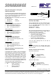
Mounting
Ultrasonic sensors shall be mounted as soft as possible in
order keep acoustic disturbances away from the mounting
spot. Thus two M18 nuts, washers and rubber sleeves for
mounting are included. The rubber sleeves for a hole of
Ø21mm shall be used.
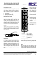
Detection beam
The detection beam of an ultrasonic sensor has the shape of
a cone. The size depends on the target and its sound
reflecting characteristics. Small and more badly reflecting
objects result in a smaller cone (narrower and shorter).
Bigger objects and those with surfaces which are not
perpendicular to the central axis can expand the cone. The
exact cone shape and size can be determined only at the
object itself. No disturbing objects must be between the
sensor and the target within the cone. Otherwise the sensor
would detect the disturbing object instead of the desired
target.
Beside the three typical
cone shapes for the UPR-
A sensors are shown
(small, medium and large
cone). Furthermore, the
size of the detection beam
is influenced by air
temperature and humidity.
The colder and dryer the
air, the larger is the beam.
On UPR-A sensors three
different cones can be
programmed by the user.
This is e.g. helpful when
sensing into small
containers or between
narrow gaps.
The cone size is set by
connecting the teach input
for >5s with the power
supply –U
B
(0V):
• Small cone: Teach 5...10s with -U
B
(yellow LED blinks fast)
• Medium cone: Teach 10...15s with -U
B
(yellow/red LED blinks fast)
• Large cone: Teach 15...20s with -U
B
(red LED blinks fast)
Inclination angle of object
Smooth surfaces can be detected up to an inclination angle
of 10°. However rough and structured (granular) surfaces
can be detected up to much higher angles. In retroreflective
mode the angle does not matter at all.
Cable
The sensors have an M12 4-pin connector for screw
mounting. The cable should not be mounted parallel or close
to high current cables. Cables have to be ordered separately.
Loch Ø21 / Hole Ø21
2 Gummiringe
2 rubber sleeves