
Datasheet


SONARANGE UPR-A 04.17 e
This Information corresponds to the current state of knowledge. SNT reserves the right to make technical changes. Do not use these products in any application
where failure of the product could result in personal injury. Liability for consequential damage resulting from the use of SNT products is excluded.
SNT Sensortechnik AG, Hammerstrasse 6, CH-8180 Bülach, Switzerland, Phone +41 44 817 29 22, Fax +41 44 817 10 83, info@sntag.ch 3/6
www.sntag.ch
1
2
3
4
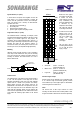
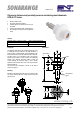
1 +24VDC (braun/brown)
2 Teach/Sync. (weiss/white)
3 0V (blau/blue)
4 OUT 0...10V / 4...20mA (schwarz/black)
1
2
3
4
1 +24VDC (braun/brown)
2 Teach/Sync. (weiss/white)
3 0V (blau/blue)
4 OUT PNP/NPN (schwarz/black)
Setting the switching points in scanning mode
UPR-A 1500 TVPA 24 C(W)
In scanning mode the target partially reflects the ultrasound
which is then detected by the sensor. The switching points
are set by connecting the teach input with either the power
supply –U
B
(0V) or +U
B
(+24VDC) for 1…5s.
The blinking LED shows during teaching if the sensor has
detected the object.
• LED blinks yellow: detected
• LED blinks red: not detected
Window operation NO
• Place the object at the near switching point
• Teach 1…5s switching point with –U
B
• Place the object to the far switching point
• Teach 1…5s switching point with +U
B
Window operation NC
• Place the object at the near switching point
• Teach 1…5s switching point with +U
B
• Place the object to the far switching point
• Teach 1…5s switching point with -U
B
Switching point NO
• Place the object at the switching point
• Teach 1…5s switching point with +U
B
• Let the sensor look into the empty space (>1.5m)
• Teach 1…5s with -U
B
Switching point NC
• Place the object at the switching point
• Teach 1…5s switching point with –U
B
• Let the sensor look into the empty space (>1.5m)
• Teach 1…5s with +U
B
Setting the switching point in retroreflective mode
UPR-A 1500 TVPA 24 C(W)
In retroreflective mode a reflector is used in the background
of the scenery (max. 1.5m away from sensor). In contrast to
optical sensors the reflector can be of any material, which is
able to reflect the sound. Retroreflective mode is used
instead of scanning mode when the target is in a small angle
to the sensor beam (see below sketch) or when it is very
sound absorbing, i.e. when not sufficient sound is reflected.
In this mode the sensor permanently checks whether it sees
the reflector or if it is covered by the target. Furthermore the
sensor has no blind range in retroreflective mode.
In retroreflective mode the reflector is teached as follows.
• NO: Teach 5...10s with +U
B
(yellow LED blinks fast)
• NC: Teach 10...15s with +U
B
(red LED blinks fast)
Setting the measuring limits analogue output
UPR-A 1500 TOR 24 C(W)AI
The two measuring limits are set by connecting the teach
input with either the power supply –U
B
(0V) or +U
B
(+24VDC)
for 1…5s. The blinking LED shows during teaching if the
sensor has detected the object.
LED blinks yellow: detected
LED blinks red: not detected
With -U
B
the lower measuring limit (0V or 4mA) and with +U
B
the upper measuring limit (10V or 20mA) is taught. Thus it is
possible to teach a rising or a falling ramp.
• Place the object at the lower measuring limit
(i.e. where 0V or 4mA is expected)
• Teach 1...5s lower measuring limit with –U
B
• Place the object at the upper measuring limit
(i.e. where 10V or 20mA is expected)
• Teach 1...5s upper measuring limit with +U
B
Lower and upper measuring limits can also later be
programmed individually.
Caution:
The teach wire must not be connected during normal
operation. The sensor can e.g. be operated after teaching
with a 3 wire cable.
Electrical connections (view to the sensor)
UPR-A 1500 TVPA 24 C(W)
UPR-A 1500 TOR 24 C(W)AI
Objekt / Target
Reflektor / reflector