
Replacement Part List
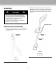
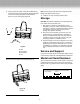

3. After sliding lower tube (B) inside the upper tube (A), line
up the screw holes on each tube (Figure 3).
4. Locate in the Parts Bag the slotted screw (C) and the
countersunk nut (D). Insert the screw through the aligned
holes in the upper and lower tubes and secure other end
with the nut.
Note: You may have to carefully move the wiring inside
the tube to one side if it blocks the path of the screw.
(Use the shipping wire provided; do not use a sharp tool.)
5. Loosen the adjustable handle and reposition until it
reaches the optimum length for the principal operator,
then retighten the bolt in Figure 4. (Readjust for each
subsequent operator.)
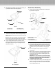
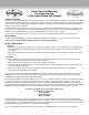
Power Base Assembly
1. Position the power base (G) beneath the handle support
(H) as shown in Figure 5-2.
Figure 5-1
Figure 5-2
Figure 5-3
F. Power base connector
G. Power base
H. Handle support
I. 2 Phillips-head screws
H
G
I
F
2. Pull the power base connector (F) out of the power base
(G). Push to snap together the connector on the handle
support to the power head’s connector; only one position
is possible, and they should t without forcing (Figure
5-1).
3. Push the coupled connectors back into the motor
compartment.
4. With the Snow Joe decal on the handle support (H) facing
you, line up the grooves in the handle support (H) with
the grooves in the power base, and slide together until
interlocked (Figure 5-3).
IMPORTANT: If you encounter any resistance, STOP!
Possibly the wiring and connectors are out of position;
in that case, reinsert them with care into the motor
compartment and repeat step 4.
5. Locate two Phillips-head screws (I) in the Parts Bag. Insert
the rst screw into the hole in back of the handle support
and turn until tight. Insert the second screw into second
hole and tighten (Figure 5-3).
Figure 3
A. Upper tube C. Slotted screw
B. Lower tube D. Countersunk nut
A
B
C
D
Figure 4
E. Carriage Bolt
E
4