AB48 HSRT Operator Manual Manual part number 508156-000 for serial numbers 4611 to current (07-07)
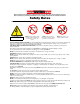
! WARNING ! All personnel shall carefully read, understand and follow all safety rules and operating instructions before operating or performing maintenance on any UpRight Powered Access aerial work platform. Safety Rules Electrocution Hazard THIS MACHINE IS NOT INSULATED! Tip Over Hazard NEVER elevate the platform or drive the machine while elevated unless the machine is on a firm, level surface.
NOTES 2
CONTENTS SECTION Page Introduction 4 A, Description of Equipment 5 B, Technical Specification 6 C, Working Envelope 7 D, Operator Requirements 8 E, Warning Notices 9 . Beaufort Scale 10 F, Pre-Start Checks 11 G, Vehicle Controls 13 H, Driving The Vehicle 15 I, Setting Up 16 J, Extending The Structure 18 . Basket Controls 18 . Ground Controls 19 K, Safety Harness L, Emergency Controls 20 . Emergency Stops 20 . Emergency Lower (Electrically) 21 .
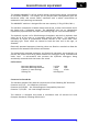
INTRODUCTION The AB46HSRT impressive 14.63m (48ft.) platform height and 7.90m (26ft.) outreach is achieved from only a 2.4m (7.9ft.) jacking width. ‘A’ frame hydraulic outriggers level the Pioneer on sloping or uneven ground. The AB48HSRT can be levelled on ground with a maximum slope of approximately 5 degrees front-to-rear or side-to-side, with the proviso that all 4 wheels are clear of ground contact.
SECTION A DESCRIPTION OF EQUIPMENT The UpRight AB48HSRT is of the parallel linkage vertical boom design, mounted on an all terrain platform. The unique, yet very simple boom configuration gives the maximum safety and control ability combined with a robust construction to withstand a heavy working environment The AB48HSRT machine is designed for two man capacity (215kg (474lb.)S.W.L.). The machine incorporates a bottom boom with tie-rod, a short vertical boom and a top boom with a telescope section.
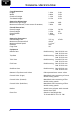
SECTION B TECHNICAL SPECIFICATION Cage Dimensions Length Width Guard-rail Height Toe-board Height 1.20m 0.80m 1.10m 0.15m 3.9ft 2.6ft. 3.6ft. 0.5ft. Operating Dimensions Maximum Cage Height Maximum Outreach ( From centre of rotation ) 14.80m 7.90m 48ft. 26ft. Closed Dimensions Overall Length Overall Height Overall Width Weight 6.10m 2.27m 1.90m 3,500kg 20.3ft. 9ft 6.3ft. Operating Parameters Safe Working Load Maximum Horizontal Pull Maximum Wind Speed Rotation Cage Slew 215 kg 400 N 12.
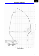
SECTION C WORKING ENVELOPE Height in Meters m m Distance in Meters 7
SECTION D OPERATOR REQUIREMENTS 1. To operate the machine you must be medically fit and have no problems with eyesight or hearing. 2. You must have a good head for heights. 3. Your primary concern must be the safe operation of the work platform, the safety of the people working with you, and the safety of other persons in your working area. 4. You must be familiar with the contents of this manual, and at no time attempt to operate the machine beyond the recommended limits. 5.
SECTION E WARNING NOTICES 1. DO NOT operate this machine unless you have been fully trained in its safe use. 2. DO NOT operate the machine on soft, slippery or sloping ground unless adequate precautions have been taken. The stabilisers are designed to operate on firm level ground with a minimum bearing strength of 50N/cm2. The maximum load imposed by an outrigger is 1.
SECTION E WARNING NOTICES 9. DO NOT move the machine with the basket raised and never allow cage or booms to slew into the path of oncoming vehicles. 10. DO NOT operate the machine if the wind speed exceeds 12.5 m/s. Be aware that, when working near high buildings or structures, shielding and funnelling effects may cause high wind forces on days when the nominal wind speed in the open is low.
SECTION F PRE START CHECK The following Pre-Start Checks should be carried out before taking the machine to the place of work. 1. Damaged or Loose Fittings. Visually Inspect the whole machine for signs of wear and tear, damage, loose or missing parts. 2. Wheels. Check tyres are at the correct pressure, AB48HSRT = 58psi (4 bar). 3. Hydraulic fluid. The hydraulic oil tank is located below the foot well on the left hand side of the vehicle.
SECTION F PRE START CHECK 5. Emergency Stop Switches. (Ref, section L) Emergency stop switches must operate correctly. Check that each stops the machine’s controls and that restarting is prevented until all stop switches are unlatched. 6. Emergency Lower/Slew. (Ref, section L) With the top and bottom booms raised approximately 500mm each and the unit switched off, check: The emergency lower switch located in the basket and ground control stations, lowers the booms when operated.
SECTION G VEHICLE CONTROLS Driving instruments & Controls Steering Wheel Lighting Panel Instrument Panel Left Hand Stalk Right Hand Stalk Foot Brake Accelerator Park Brake Instrument Panel Hour Meter Beacon Horn Ignition Switch Fuse Box 13
SECTION G VEHICLE CONTROLS Battery Charge Lamp Engine Temp Lamp Oil Pressure Warning Lamp Air Filter Blocked Lamp Low Speed Lamp High Speed Lamp Low Fuel Warning Lamp Neutral Gear Lamp Engine Pre Heat Lamp Lighting Panel Light Switch 3 positions Instrument Indicators Hazard Warning Lights Stalk Functions 14 Fog Light Switch
SECTION H DRIVING THE VEHICLE 1. Ensure that the booms are fully lowered and located in the front prop, all outriggers are fully raised and that the machine is manoeuvrable. 2. Climb into the driving seat and fasten seat belt across your lap. 3. Insert the ingition Key and turn part way, intil the Pre-Heat lamp h illuminated. (Ref, Section G) ! 4. a s Do NOT use the Steering wheel to pull yourself into the cab as this could cause damage to the vehicles Steering system.
SECTION I SETTING UP 1. Park the unit in an appropriate location at the workplace. 1 Do not attempt to set up the machine on steep slopes, ramps or soft ground. 2. Select Neutral, apply the Park brake to the vehicle, and leave the engine running. 3. Lift the Outrigger control cover hatch, located at the side of the driving seat. 4. Lower the outriggers by operating the ‘Deadman’ push button and operating the outriggers two at a time until they are all in contact with the ground.
SECTION I SETTING UP The centre console electrical box displays LED’s corresponding to each outrigger leg. These LED’s will light when the associated outrigger leg has extended enough for the machine to be stable when lifting. Continue lowering the machine until all the LED’s have been lit. 5. By using the Level indicator, lower opposite Outriggers until the bubble and indicator ring are concentric (i.e., the bubble rests in the centre).
SECTION J EXTENDING THE STRUCTURE 1. Ensure that the engine is running, and the Outriggers are correctly deployed. 2. At the Control Station, turn the key switch key to ‘Basket’. Basket 3. Climb into the basket. The platform may now be raised, lowered or slewed in any direction by operating the control levers at the basket, whilst depressing the motor run footswitch (DEADMAN). 4. The basket is fitted with an automatic overload sensor coupled to an audible siren and a flashing beacon.
SECTION J EXTENDING THE STRUCTURE 6. A duplicate set of controls (excluding Slew Basket and Basket Trim) is mounted on the Slew Turret under the right hand side cover, which allows the platform to be operated from the Ground. 7. At the Ground Control Station, turn the key to ‘Ground’ Ground 8.
SECTION K SAFETY HARNESS & EMERGENCY CONTROLS 1. In accordance with IPAF recommendations, UpRight recommend the use of a Full Body Harness with an adjustable lanyard is used when operation from the basket. 2. The lanyard length should be as short as possible. 3. A permanent attachment point is provided in the basket for fixing the harness. EMERGENCY CONTROLS 1. Emergency Stop Emergency Stop buttons are fitted on the machine to stop the motor in an emergency.
SECTION L EMERGENCY CONTROLS 2. Emergency Lower. In the event of a power failure, There are two ways of Safely lowering the basket. Emergency Lowering, method one The operator or someone on the ground, can lower the booms to a safe position by activating the Emergency lowering selector switch both ways, o n the Basket Control Panel and the Ground Control Panel. The Flick Boom cannot be lowered by activating the Emergency Lowering Switch.
SECTION L EMERGENCY CONTROLS Emergency Lowering a, method two. In the event of a power failure, the emergency lowering hand pump can be operated from the driver side foot well, choosing between the boom controls and slewing functions on the 3 way operation valve. To operate the hand pump, simply insert the lever into the pump shaft, then lower the lever to a convenient position to start pumping The boom lowering control can be chosen by the vertical position.
SECTION L EMERGENCY CONTROLS 3. EMERGENCY SLEW If a loss in power has occurred, the slew can be operated by hand. To do this: Wind out spindle on right hand side of hydraulic manifold block Spindle Locate 17mm socket (located in vehicle tool box) on to slew drive hex shaft and rotate as required to position slew the machine. Ensure that the spindle is wound in fully for normal use once the problem has been rectified.
SECTION M STOWING THE MACHINE Fully lower both main booms, flick boom and ensure that the basket is level. Ensure that the tele boom is fully retracted and that the bottom boom is located in the front Boom Prop, making the boom down switch. By alternating from front to rear, carefully inch up each pair of Outriggers until all four Outriggers are fully retracted, and the road wheels are in contact with the ground. Now fully raise the outriggers until they are in the stowed position.
SECTION N MAINTENANCE The unit must have a thorough inspection carried out every 6 months in accordance with LOLER Regulations 1998 and a Certificate of Thorough Inspection produced by a competent person. 1 Always ensure the machine structure is in good, sound, undamaged condition. Any inspection procedure is always aided by keeping the machine clean. NB. Do not steam clean the battery charger or electrical components. ! Daily Checks. 1. Damaged or Loose Fittings.
SECTION N MAINTENANCE 1 The unit must have a thorough inspection carried out every 6 months in accordance with LOLER Regulations 1998 and a Certificate of Thorough Inspection produced by a competent person. ! Always ensure the machine structure is in good, sound, undamaged condition. Any inspection procedure is always aided by keeping the machine clean. NB. Do not steam clean the electrical components. Weekly Checks. 1. Apply grease to the slew gear wheel and all grease nipples. Slew Drive Gears.
NOTES 27
Local Distributor: Lokaler Vertiebshändler: Distributeur local: El Distribuidor local: Il Distributore locale: USA Europe TEL: +1 (559) 443 6600 FAX: +1 (559) 268 2433 TEL: +44 (0) 845 1550 058 FAX: +44 (0) 195 2299 948 www.upright.