
User guide

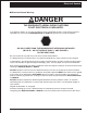


Table of Contents
Electrical Hazard
Electrical Hazard Warning . . . . . . . . . . . . . . . . . . i
Minimum Safe Approach Distance . . . . . . . . . . . ii
Table 1 - (M.S.A.D.). . . . . . . . . . . . . . . . . . . . . . ii
Figure 3 - (M.S.A.D.) . . . . . . . . . . . . . . . . . . . . . ii
Introduction
Signs. . . . . . . . . . . . . . . . . . . . . . . . . . . . . . . . . . iii
Qualified operators . . . . . . . . . . . . . . . . . . . . . . . iii
Operation rules. . . . . . . . . . . . . . . . . . . . . . . . . . iii
Maintenance. . . . . . . . . . . . . . . . . . . . . . . . . . . . iii
Responsibilities of parties . . . . . . . . . . . . . . . . . iv
OSHA, ANSI and CSA Standards . . . . . . . . . . . iv
California Proposition 65 warning . . . . . . . . . . . iv
Options. . . . . . . . . . . . . . . . . . . . . . . . . . . . . . . . iv
Additional information. . . . . . . . . . . . . . . . . . . . . iv
1. Safety
Safe Operation. . . . . . . . . . . . . . . . . . . . . . . . . 1-1
Pre-start Inspection. . . . . . . . . . . . . . . . . . . . 1-1
Work Place Inspection and Practices . . . . . . 1-1
Electrocution . . . . . . . . . . . . . . . . . . . . . . . . . 1-2
Tipover and Falling Hazards . . . . . . . . . . . . . 1-2
Crushing . . . . . . . . . . . . . . . . . . . . . . . . . . . . 1-2
General Safety Precautions. . . . . . . . . . . . . . . 1-2
Personnel Precautions . . . . . . . . . . . . . . . . . 1-2
Operator General Precautions . . . . . . . . . . . 1-2
Mounting and Dismounting Precautions . . . . 1-2
Starting and Stopping Precautions . . . . . . . . 1-3
Operating Precautions . . . . . . . . . . . . . . . . . 1-3
Operator Maintenance Precautions . . . . . . . 1-3
Safety Decals and Placards . . . . . . . . . . . . . . 1-3
2. Safety Devices
Safety device information . . . . . . . . . . . . . . . . 2-1
Emergency Power Battery. . . . . . . . . . . . . . . 2-1
Emergency stop switches . . . . . . . . . . . . . . . 2-1
Flashing Lights . . . . . . . . . . . . . . . . . . . . . . . 2-2
Platform Foot Switch . . . . . . . . . . . . . . . . . . . 2-2
GFCI (Ground Fault Circuit Interrupt) . . . . . . 2-2
Platform Gravity Gate . . . . . . . . . . . . . . . . . . 2-2
Ground Operation Switch. . . . . . . . . . . . . . . 2-3
Platform Guardrails . . . . . . . . . . . . . . . . . . . . 2-3
Operator Horn . . . . . . . . . . . . . . . . . . . . . . . . 2-3
Lanyard Anchor Points . . . . . . . . . . . . . . . . . 2-3
Level Sensor . . . . . . . . . . . . . . . . . . . . . . . . . 2-4
Motion Warning Alarm. . . . . . . . . . . . . . . . . . 2-4
Platform Swinging Gate . . . . . . . . . . . . . . . . 2-4
Tilt Alarm . . . . . . . . . . . . . . . . . . . . . . . . . . . . 2-4
3. Specifications
General Specifications. . . . . . . . . . . . . . . . . . . 3-1
Model drawing and overall dimensions . . . . . . 3-2
Working envelope . . . . . . . . . . . . . . . . . . . . . . 3-3
Nomenclature and serial numbers . . . . . . . . . 3-4
Right hand side of chassis and turntable . . . 3-4
Left hand side of chassis and turntable . . . . 3-4
4. Gauges, Circuit Breakers and Displays
Gauges . . . . . . . . . . . . . . . . . . . . . . . . . . . . . . 4-1
Ammeter . . . . . . . . . . . . . . . . . . . . . . . . . . . . 4-1
Hour Meter . . . . . . . . . . . . . . . . . . . . . . . . . . 4-1
Hydraulic Oil Filter. . . . . . . . . . . . . . . . . . . . . 4-1
Hydraulic Oil Level . . . . . . . . . . . . . . . . . . . . 4-2
Hydraulic Oil Temperature. . . . . . . . . . . . . . . 4-2
Circuit Breakers . . . . . . . . . . . . . . . . . . . . . . . . 4-2
GFCI Circuit Breaker. . . . . . . . . . . . . . . . . . . 4-3
Battery Charger Circuit Breaker . . . . . . . . . . 4-3
Electronic Display . . . . . . . . . . . . . . . . . . . . . . 4-3
5. Batteries and Battery Charging
Batteries . . . . . . . . . . . . . . . . . . . . . . . . . . . . . 5-1
Battery charging . . . . . . . . . . . . . . . . . . . . . . . 5-2
6. Controls
Controls Description . . . . . . . . . . . . . . . . . . . . 6-1
Controls and Control Decals Locations. . . . . 6-1
Electronic Display Window . . . . . . . . . . . . . . 6-1
Ground Control Box. . . . . . . . . . . . . . . . . . . . . 6-2
Ground Control Box Controls . . . . . . . . . . . . 6-3
Platform Control Box . . . . . . . . . . . . . . . . . . . . 6-4
Platform Control Box Controls. . . . . . . . . . . . 6-5
Electronic Display . . . . . . . . . . . . . . . . . . . . . . 6-5
Information messages. . . . . . . . . . . . . . . . . . 6-5
Wait messages . . . . . . . . . . . . . . . . . . . . . . . 6-5
Operator Action messages . . . . . . . . . . . . . . 6-5
Service Required messages . . . . . . . . . . . . . 6-5
Electronic Display Message Tables . . . . . . . . . 6-6
Information message table . . . . . . . . . . . . . . 6-6
Wait message table. . . . . . . . . . . . . . . . . . . . 6-6
Operator Action message table. . . . . . . . . . . 6-7
Service Required message table . . . . . . . . . 6-8
Platform Foot Switch . . . . . . . . . . . . . . . . . . . . 6-9
Chassis Controls . . . . . . . . . . . . . . . . . . . . . . . 6-9
Battery Switch . . . . . . . . . . . . . . . . . . . . . . . . 6-9
Battery Charger. . . . . . . . . . . . . . . . . . . . . . . 6-9
AB46J – 0163187 page - v