P/N 0163187 February, 2001
LIMITED WARRANTY Snorkel warrants each new machine manufactured and sold by it to be free from defects in material and workmanship for a period of one (1) year from date of delivery to a Customer or for one year after the machine has been placed in first service in a Dealer rental fleet, whichever comes first.
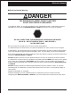
Electrical Hazard ■ Electrical Hazard Warning DANGER THE SNORKELIFT AERIAL WORK PLATFORM IS NOT ELECTRICALLY INSULATED. If the platform, booms, or any other conductive part of a Snorkelift contacts a high-voltage electrical conductor, the result can be SERIOUS INJURY or DEATH for persons on or near the machine. GO NO CLOSER THAN THE MINIMUM SAFE APPROACH DISTANCES (M.S.A.D) - AS OUTLINED IN TABLE 1. AND FIGURE 3., ON THE NEXT PAGE. Be sure to allow for sag and sway in the wires and the work platform.
Electrical Hazard ■ Minimum Safe Approach Distance The Snorkelift is an all metal boom, NOT ELECTRICALLY INSULATED, aerial work platform. DO NOT operate it near ELECTRICAL conductors. Regard all conductors as being energized. Use the table and illustration below to determine safe clearance from electrical conductors. Table 1 and Figure 3 are reprinted courtesy of Scaffold Industry Association, ANSI/SIA A92.5, page 23. ❑ Table 1 - (M.S.A.D.
Introduction The most important chapter in this manual is "Safety" chapter 1. Take time, now, to study it closely. The information in chapter 1, might save your life or prevent serious injury. ■ Signs The following three conventions are used throughout this manual. 1. Danger sign DANGER means: Attention! Become alert! Your safety is involved. 2.
Introduction ■ Responsibilities of parties It is imperative that all owners and users of the Snorkelift read, understand, and conform to all applicable regulations. Ultimate compliance to OSHA regulations is the responsibility of the employer using the equipment. DANGER ANSI Standard A92.5-1992 clearly identifies requirements of all parties who might be involved with Boom-Supported Elevating Work Platforms.
Table of Contents Electrical Hazard 3. Specifications Electrical Hazard Warning . . . . . . . . . . . . . . . . . . i Minimum Safe Approach Distance . . . . . . . . . . . ii Table 1 - (M.S.A.D.). . . . . . . . . . . . . . . . . . . . . . ii Figure 3 - (M.S.A.D.) . . . . . . . . . . . . . . . . . . . . . ii General Specifications. . . . . . . . . . . . . . . . . . . 3-1 Model drawing and overall dimensions . . . . . . 3-2 Working envelope . . . . . . . . . . . . . . . . . . . . . .
Table of Contents 7. Daily Inspection and Maintenance 10. Stowing and Transporting Daily Inspection and Maintenance Table . . . . . 7-1 Wiring harnesses. . . . . . . . . . . . . . . . . . . . . . . 7-2 Battery terminals . . . . . . . . . . . . . . . . . . . . . . . 7-2 Battery fluid level . . . . . . . . . . . . . . . . . . . . . . . 7-3 Hydraulic oil . . . . . . . . . . . . . . . . . . . . . . . . . . . 7-3 Hydraulic oil leaks . . . . . . . . . . . . . . . . . . . . . . 7-3 Tires. . . . . . . . . . . . .
1. Safety ■ Safe Operation The following safety information is vitally important for safe operation of the AB46J. Failure to follow these instructions can result in personal injury or DEATH. ❑ Pre-start Inspection Prior to each shift, the AB46J shall be given a visual inspection and function test. See the “Daily Inspection and Maintenance” chapter 7, in this manual for a list of items to inspect and test.
1. Safety ❑ Electrocution The AB46J is an all metal boom, NONINSULATED, aerial work platform. DO NOT operate it near ELECTRICAL conductors. Regard all conductors as being energized. DO NOT operate outside during a thunderstorm. ❑ Tipover and Falling Hazards DO NOT operate an AB46J from a position on trucks, trailers, railway cars, floating vessels, scaffolds, or similar equipment unless the application is approved in writing by Snorkel.
1. Safety ❑ Starting and Stopping Precautions ■ Safety Decals and Placards DO NOT start until all personnel are clearly away from the machine. There are several safety decals and placards on the AB46J. Their locations and descriptions are shown in this section. Take time to study them. Before leaving the operator’s station, place the machine in the stowed position.
1.
1.
2. Safety Devices ■ Safety device information ❑ Emergency stop switches For emergency operation controls and procedures, see the “Emergency Operation” chapter 9, in this manual. The devices listed in this chapter are safety devices. They are on an AB46J to increase safety in the work place for both the operator and other people near an AB46J. DO NOT by-pass, disable, modify, or ignore any of these devices.
2. Safety Devices ❑ Flashing Lights ❑ GFCI (Ground Fault Circuit Interrupt) The optional flashing lights alert people that the AB46J is present. The lights flash at about one flash per second any time the Battery switch, Master Key Switch, and the Emergency Stop switch (at the ground) are all ON. There is no ON/OFF switch for the flashing lights. The (GFCI) ground fault circuit interrupt is located near the platform control box.
2. Safety Devices ❑ Ground Operation Switch ❑ Operator Horn The operator horn is used primarily to get the attention of people on the ground when you are working aloft. For the horn to work the Battery switch must be ON and the following switches, on the ground control box, must be set as indicated: The Ground Operation switch prevents the platform from moving if something accidentally pushes one of the platform moving switches at the ground control box. Platform/Ground Selector . . . . . .
2. Safety Devices ❑ Level Sensor ❑ Tilt Alarm The level sensor detects how far out of level the turntable is. If the turntable gets over 5° out of level the level sensor activates the tilt alarm (described in this chapter). The tilt alarm warns the AB46J operator that the AB46J is over 5° out of level. ❑ Motion Warning Alarm The optional motion warning alarm emits a loud beeping sound, at ground level, anytime the Drive/Steer controller is in FORWARD or REVERSE or anytime the booms move.
3. Specifications The Snorkelift AB46J is a boom-supported elevating work-platform built to conform to all applicable OSHA, ANSI or CSA standards as previously outlined. ■ General Specifications Working height (nominal) . . . . . 52 ft - 0 in (15.8 m) Platform height (maximum) . . . . 46 ft - 0 in (14.0 m) Platform reach (maximum) . . . . . 24 ft - 8 in (7.5 m) Length, overall (booms down and retracted). . . 19 ft - 1 in (5.8 m) Width, overall . . . . . . . . . . . . . . . . 5 ft - 9 in (1.
3.
3.
3.
4. Gauges, Circuit Breakers and Displays ■ Gauges Time will also accumulate when: ❑ Ammeter Battery charger is disconnected, Battery switch . . . . . . . . . . . . . . . . . . . . . . . ON Platform/Ground Selector . . . . . . PLATFORM Emergency Stop (ground). . . . . . . . . . . . . . ON Master Key switch . . . . . . . . . . . . . . . . . . . . ON Emergency Stop (platform). . . . . . . . . . . . . ON Foot Switch . . . . . . . . . . . . . . . . . . Stepped On The hour meter gauge cannot be reset.
4. Gauges, Circuit Breakers and Displays ❑ Hydraulic Oil Level ❑ Hydraulic Oil Temperature The hydraulic oil level gauge (1) is on the side of the hydraulic oil tank (2). The hydraulic oil temperature gauge measures the temperature of the oil in the tank. The temperature should not exceed 200°F (93°C). If the temperature reaches its limits, reduce your driving speed or stop the AB46J and let the hydraulic oil cool.
4. Gauges, Circuit Breakers and Displays ❑ GFCI Circuit Breaker ❑ Battery Charger Circuit Breaker If the 15 A circuit breaker on the GFCI outlet trips, disconnect whatever is plugged into the outlet, wait one minute, then press the circuit breaker button back in. If the circuit breaker trips a second time, refer the problem to a qualified service technician. If the circuit breaker in the battery charger trips, wait one minute then press the circuit breaker back in.
5. Batteries and Battery Charging ■ Batteries The following information about battery care and maintenance was supplied by Interstate Batteries and is reprinted here with their permission. 1. New batteries need to be cycled several times before reaching full capacity (20-50 cycles, depending on type). Use should be limited during this period. 2. Always fully recharge batteries immediately after use. Batteries perform best when they are fully charged.
5. Batteries and Battery Charging ■ Battery charging CAUTION DO NOT leave the battery charger on for more than two days. The batteries might be severely overcharged and/or damaged if the charger fails to automatically turn off. Keep all battery charger ventilation ports open to prevent accumulation of explosive gasses and heat. 1. Turn the Master Key Switch on the ground control box to OFF and the Battery switch (1) ON. 4. Visually inspect the ammeter (4) for proper charging rate.
6. Controls ■ Controls Description This chapter shows the controls at the ground control box and the platform control box, and explains what each control does. This chapter DOES NOT explain how to use the controls to produce useful work. “Operation” chapter 8, covers the proper use of controls. See the “Emergency Operation” chapter 9, for correct emergency operation procedures. See the “Options” chapter 11, for correct operation procedures of any optional equipment.
6. Controls ■ Ground Control Box Controls for operating the AB46J from the ground, are located on the right side of the turntable. The number of each control below corresponds to the control’s call out on the control box illustration. 1. Emergency Stop: Press the red button in, at any time, under any conditions, and the entire machine stops — the drive motors and pump turn off, the brakes automatically set, and nothing moves. This switch must be out for anything on the machine to work. 2.
6.
6. Controls ■ Platform Control Box Controls for operating the AB46J from the platform are located on the platform control box, with the exception of the foot switch which is on the platform floor. The number of each control below corresponds to the control’s call-out on the control box illustration. 1. Emergency Stop: Press the large red button down at any time, under any conditions, and the entire machine stops — the drive motors and pump turn off, the brakes automatically set, and nothing moves.
6. Controls ❑ Platform Control Box Controls Electronic Display window ■ Electronic Display The Electronic Display automatically turns on when the AB46J is set for platform control box operation. The Emergency Stop switch (1) MUST be ON (pulled up), to provide power to the Electronic Display to show a message. The display can show four different types of messages about the status of the drive system and two service status messages: 1. Information messages 2. Wait messages 3. Operator Action messages 4.
6. Controls ■ Electronic Display Message Tables The following tables list the four types of messages that the Electronic Display will indicate and an explanation of each message. ❑ Information message table Electronic display message: DRIVE SYSTEM CHECK ***SYSTEM OK!*** CLOSE FOOT SWITCH TO TEST BATTERY NEUTRAL VEL = 0.0 MPH BATT E F Explanation of message: This is the first message to appear after the platform control box is turned on.
6. Controls ❑ Operator Action message table Electronic display message: CENTER JOYSTICK INITIAL STARTUP CENTER JOYSTICK JOYSTICK IS FORWARD CENTER JOYSTICK JOYSTICK IS BACK CENTER JOYSTICK TOO FAST FOR GRADE CHARGE BATTERIES BATTERY VOLTS LOW INCLINE TOO STEEP MOTOR STALLED CYCLE FOOT SWITCH TO DRIVE Explanation of message: This message occurs immediately after the system diagnostic has been performed if the Drive/Steer joystick controller is not centered.
6. Controls ❑ Service Required message table Electronic display message: SERVICE REQUIRED ERROR: ARMATURE DRV SERVICE REQUIRED ERROR: ARMATURE VOLT Explanation of message: When you read any of the SERVICE REQUIRED messages, you should immediately: 1. Record the error message shown on the second line of the display. You will need this error message when you contact a qualified service technician for repairs. 2. Take the AB46J out of service IMMEDIATELY. 3.
6. Controls ■ Platform Foot Switch ❑ Battery Charger Set the Battery switch to ON and connect the battery charger to a source of power. You must step down on the platform foot switch, and hold it down, when you use any platform control that causes the platform to move. Stepping on the platform foot switch activates the other switches and controls in preparation to do work. The foot switch is to the platform control box what the Ground Operation switch is to the ground control box.
7. Daily Inspection and Maintenance At the start of each work day (or 8 hour shift), an AB46J qualified operator must perform the Daily Inspection and Maintenance as listed in the table below. Defective parts and/or equipment malfunctions jeopardize the safety of the operator and other personnel, and can cause damage to the machine. DANGER The purpose of the Daily Inspection and Maintenance is to keep the AB46J in proper working condition and to detect signs of malfunction at the earliest possible time.
7. Daily Inspection and Maintenance The rest of this chapter shows how to perform the inspection and maintenance required for each item in the Daily Inspection and Maintenance Table. ■ Battery terminals ■ Wiring harnesses Battery terminals should be clean and free of corrosion and dirt. Inspect all the wiring harnesses on the machine for loose connections, broken wires, and frayed insulation.
7. Daily Inspection and Maintenance ■ Battery fluid level ■ Hydraulic oil leaks DANGER Leaking hydraulic oil can cause burns, fires, falls (slipping), cuts, and puncture wounds (if under high pressure). Have a qualified trained maintenance person repair all hydraulic fluid leaks before you operate an AB46J. DANGER Batteries emit hydrogen and oxygen, elements that can combine explosively. DO NOT smoke or permit open flames or sparks when checking batteries.
7. Daily Inspection and Maintenance ■ Bolts and fasteners Visually inspect all fasteners to see that none is missing or obviously loose. Pay particular attention to all of the pin caps (1) and snap rings (2) that connect the booms, they should all be present and not damaged in any way. Check the turntable end of the booms and the end of the lift cylinders for other pin caps and snap rings. Check both sides of the machine.
7. Daily Inspection and Maintenance ■ Structural damage and welds ■ Lanyard anchor points Visually inspect all welds for cracks, all structural members for deformity, and all sheet metal for dents that could interfere with machine operation. Visually check the lanyard anchor points to see that they are not deformed, cut off, or cracked. ■ Platform guardrails Visually inspect the platform guardrails to see that none of the tubing has been cut out, removed, or deformed in any way.
7. Daily Inspection and Maintenance ■ Platform gravity gate ■ Flashing lights Inspect the platform gravity gate to be sure it is present, that it moves freely, and is not damaged in any way. Visually check to see that the optional flashing lights flash at approximately one flash per second when the Battery switch, Master Key Switch, and the Emergency Stop switch (at the ground) are all ON.
7. Daily Inspection and Maintenance ■ Ground control box ■ Level sensor When you check turntable Swing at CW (1) the turntable will move directly toward you. Be sure you have room to step backward. DANGER Death or Serious Injury could occur if you should rotate the turntable into a position that would cause you to be crushed. Use Riser Lift to raise the platform about six feet (2 m).
7. Daily Inspection and Maintenance ■ Emergency power DANGER When the turntable rotates clockwise (CW) it will move directly toward you. When you check turntable Swing at CW (1) be sure you have room to step backward. Use the Emergency Power switch (5), to check all positions of each control. For correct emergency power operating procedures see the “Emergency Operation” chapter 9. ■ GFCI (Ground Fault Circuit Interrupt) Connect a source of 125 volt AC power to the power plug at the back of the chassis.
7. Daily Inspection and Maintenance ■ Slide pads ■ Hydraulic oil filter To check the condition of the hydraulic oil filter do the following: 1. Be sure the battery charger is disconnected. Use ground control box to extend the inner boom about 1 foot (30 cm). Inspect to see that all slide pads are in place in the rear end of base boom. 2. Set the Battery switch (1) to ON. Look at the surface that slides on each slide pad.
7. Daily Inspection and Maintenance ■ Placards and decals Look to see that all placards and decals are in place and legible. Replace any missing or illegible placards or decals before placing the Snorkelift into service for the daily work shift. Decal and placard kits for the AB46J are available from Snorkel dealers.
7. Daily Inspection and Maintenance ❑ Inspection drawing number 1 14 23 30 15 8 C 28 C 20 22 25 25 A - Sandblast option only. 7 12 16 A - Airline to platform option only.
7.
8. Operation ■ Operating Procedures ■ Emergency Stopping This chapter explains how to properly start and operate an AB46J. Read and understand all the previous chapters in this manual before you begin to operate an AB46J. To stop an AB46J, push either the Emergency Stop button at the ground control box or at the platform control box in. CAUTION If you use the AB46J for painting be sure the optional sandblast protection kit is installed to protect the hydraulic cylinder rods from paint.
8. Operation ■ Starting From Ground Control Box Before you begin to operate the AB46J from the ground control box, a qualified operator must perform the "Daily Inspection and Maintenance" as described in chapter 7, of this manual. None of the ground controls work when the battery charger is plugged in. Unplug the battery charger before you begin to operate. To start from the ground control box do the following: 5. Insert key (5) and set the Master Key Switch (6) to ON. The 46e is ready to begin work.
8. Operation 7. Pull the Emergency Stop switch (8) up (ON). 2. Set the Emergency Stop switch (2) to ON (pulled out). 3. Set the Platform/Ground Selector switch (3) to platform (up). 4. Insert the key (4) and set the Master Key Switch (5) to ON. The Emergency Stop switch MUST be on (pulled up) for the platform control box Electronic Display to show messages. After initial system diagnostics check, the system will display a message that the system is "OK!." Depress platform foot switch to test battery.
8. Operation ❑ From Ground Control Box Each of the ways the platform can move is shown in the following photograph and switch illustration: The photograph shows the platform switches that cause the platform or booms to move. Ground control box operation platform-moving switch illustration: 1. Main Boom Lift 2. Extend/Retract MAIN BOOM LIFT These platform-moving switches, (1 through 7), will produce the movement as indicated by the illustration's to the right. UP EXTEND DOWN RETRACT 3. Jib Boom 4.
8. Operation ❑ From Platform Control Box When you operate from the platform control box, be sure that the lanyard of your fall restraint is attached to an anchor point on the platform mount. Also, be sure the gate is closed. Each of the ways the platform can move is shown in the following photograph and switch illustration: The photograph shows the platform switches that cause the platform or booms to move.
8. Operation ■ Driving DANGER Death or Serious Injury can result from sudden stops. To avoid sudden stops, do not remove your foot from the platform foot switch while the AB46J is in motion. You must be stepping on the platform foot switch for the Drive/Steer controller to work. When you release the Drive/Steer controller the wheels stay where you set them. The wheels do not return to the "straight ahead" position the way automobile wheels do.
9. Emergency Operation ■ Emergency Operation Procedures The following procedures are emergency procedures only. DO NOT use them for normal operation. Their purpose is to get the platform and operator safely to ground when a problem keeps the platform from lowering in the normal way. ❑ Operation From Platform Control Box Switch settings listed in the first four steps below must exist at the ground before emergency operation procedures will work at the platform control box: 5.
9. Emergency Operation ❑ Operation From Ground Control Box 1. Set the Battery switch (1) to ON. 5. Hold appropriate platform-moving switch (6) the direction you want the platform to move. 6. Hold the Ground Operation switch (7) up. 7. Hold the Emergency Power switch (8) down and the platform will move. Boom movements will be slow and have long lag times under Emergency Power. 2. Set the Master Key Switch (2) to ON. 3. Pull the Emergency Stop switch (3) out (on). 4.
10. Stowing and Transporting ■ Stowing ■ Transporting At the end of each work day (or in preparation for lifting or storage) a qualified operator should put the AB46J into its STOWED POSITION then lock it.
10. Stowing and Transporting Driving onto transport trailer To safely drive an AB46J onto a transport trailer, observe the following steps: 1. Visually inspect the alignment of the loading ramp (1) and the truck or trailer (2). They should both be on the same straight line. 2. Chock (3) the wheels of the truck or trailer so it cannot roll away form the loading ramp (1) while the AB46J is being loaded. 3. Set ground control box for platform operation. 4.
10. Stowing and Transporting 3. Set the Battery switch to OFF and lock the Battery switch. CAUTION DO NOT run a strap over the platform toe board (3). The toe board is not strong enough to hold the platform down and will be damaged in transit. Run a strap where shown. 4. Run a nylon strap (4) over the platform support (5) to hold the platform on the blocks (1) as shown. 7. Lock the cowling doors closed. 5. Attach chains to the front (6) tie down lugs.
10. Stowing and Transporting ■ Towing ■ Lifting The Snorkelift AB46J has not been designed to be towed. An AB46J can be safely lifted. DO NOT tow an AB46J. DANGER A runaway AB46J can cause Death or Serious Injury. If you have to move an AB46J down a grade, chain a braking vehicle to the “up hill “ end of the AB46J. CAUTION However, to prevent any damage to the AB46J or injury to personnel, only a trained qualified service technician should perform lifting.
11. Options ■ Air line to platform The input to the air line is on the lower rear of the turntable. The outlet is on the platform mounting frame. The maximum safe working pressure for the air line is 250 psi (1725 kPa). If the BumpGard comes into contact with a stationary object, the BumpGard moves and one or both of the light beams is broken. A dark switch removes control from the platform control box, immediately stopping all platform movement.
11. Options ■ Motion Warning Alarm The motion warning alarm emits a very loud sound (...beep...beep...beep...), at ground level, when the Drive/Steer controller is in FORWARD or REVERSE or when one or more booms are in motion. This alarm alerts people on the ground that the AB46J is moving. ■ Platform Swinging Gate The optional platform swinging gate is designed to automatically close after you enter or leave the platform. It helps prevent people from falling off the platform.
12. Fire Fighting and Chemical Containment ■ Hazardous components ☞ Waste disposal method An AB46J contains the following materials and objects that potentially could become significant fire or environmental hazards during it's lifetime: 1. Battery, lead/acid 2. Foam in tires 3. Hydraulic oil The rest of this chapter lists manufacturer’s information you will need if you ever have to control any of the above items during an upset or emergency.
12. Fire Fighting and Chemical Containment ❑ Hydraulic Oil (UN 1270) ☞ Extinguishing media: Use water spray, dry chemical, foam, or CO2 . ☞ Special fire fighting procedures: Water or foam may cause frothing. Use water to keep fire-exposed containers cool. Water spray may be used to flush spills away from exposures. ☞ Unusual fire and explosion hazards: Products of combustion may contain carbon monoxide, carbon dioxide, and other toxic materials.
13. Operator's Troubleshooting ■ Troubleshooting All of the actions described in this chapter may be performed by an AB46J operator, a trained and qualified service technician is not required. The second column lists some of the causes for each problem. The third column lists remedies. The first column, of the following chart, lists some common problems encountered by AB46J operators.
13. Operator's Troubleshooting Problem Booms do not work Cause Accumulator bleed down valve open. Remedy Close accumulator bleed down valve. See illustration below for bleed down valve handle location. ❑ Accumulator Bleed Down Valve Noting handle position as illustrated above, completely close the bleed-down valve.
Index ! 125 volt AC power, 7-8 A additional information, A-iv Additional information See Introduction - page iv Air line to platform, 11-1 Alarms motion warning, 11-2 tilt alarm, 2-4 Ammeter, 4-1 Arrows blue and yellow, 8-6 B Battery, 5-1, 12-1 cables, 5-1 care, 5-1 charging, 5-2, 7-6 electrolyte, 5-1 fluid level, 7-3 lead/acid, 5-1, 12-1 maintenance, 5-1 Battery charger, 5-2, 6-9, 8-2 input voltage switch, 6-9 Battery terminals, 7-2 Bolts and fasteners, 7-4 Boom movement times, 3-1 stowing, 10-1 BumpGard
Index Service Required messages, 6-5 Wait messages, 6-5 System voltage, 3-1 Electrical (GFCI) Outlets at Platform, 8-6 Electrical Hazard Warning See Electrical Hazard - page i Emergency Operation Procedures, 9-1 Emergency Power Battery, 2-1 Emergency stop switches, 2-1 Environmental operating ranges, 3-1 Hydraulic oil filter, 4-1, 7-9 fluid leaks, 7-3 maximum pressure, 3-1 maximum temperature, 3-1 oil level, 4-2, 7-3 system capacity, 3-1 tank, 4-2 filler cap, 7-3 sight glass gauge, 7-3 F I Fire Fighting
Index Message table, electronic display Information message, 6-6 Operator Action message, 6-7 Service Required message, 6-8 Wait message, 6-6 Minimum Safe Approach Distance See Electrical Hazard - page ii Model drawing, 3-2 Motion Warning Alarm, 2-4 Mounting and Dismounting Precautions, 1-2 Moving The Platform , 8-3 N Nomenclature and serial numbers, 3-4 O Operating Precautions, 1-3 Operating Procedures, 8-1 Operation, 8-1 Driving forward, 8-6 reverse, 8-6 Emergency Operation From Ground Control Box, 9-2
Index Maintenance Precautions, 1-3 personnel, 1-1 rules, 1-1 safe operation, 1-1 Safety Decals and Placards, 1-3 Sandblast protection kit, 8-1 Securing for Day, 8-6 Signs, Caution, Danger, Notes See Introduction - page iii Slide pads, 7-9 Starting and Stopping Precautions, 1-3 Starting From Ground Control Box, 8-2 Starting From Platform Control Box, 8-2 Steering, 8-6 Stowing, 10-1 locking the machine, 10-1 stowed position, 10-1, 10-2 Structural damage and welds, 7-5 T Tailswing, 3-1 Tipover and Falling Haz