AB46E Operator Manual This first section of the Operator manual is the English language version. (EN) Manual part number 509648-000 for serial numbers 20000 to current.
Table of Contents Table of Contents Declaration of Conformity ...........................................2 Safety Rules ...............................................................3 Introduction .................................................................4 Component Identification ............................................4 Special Limitations......................................................5 Platform Capacity ....................................................5 Manual Force ...............
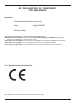
EC DECLARATION OF CONFORMITY FOR MACHINERY MACHINERY: Powered Aerial Platform known as: Type: Upright AB46E Serial Number: The machine specified above conforms to the following provisions: Machinery directive 98/37/EC (using document EC Community Legislation on Machinery and taking guidance from EN280:2001 + Amendment A1:2004) Council Directive 89/336/EEC on Electromagnetic Compatibility as amended by 93/68/EEC and 92/31/EC Council Directive 73/23/EEC on Low Voltage Equipment Safety as amended by 93/68/E
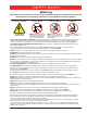
SAFETY RULES AWarning All personnel shall carefully read, understand and follow all safety rules and operating instructions before operating or performing maintenance on any UpRight aerial work platform.
Introduction When contacting UpRight for service or parts information, be sure to include the MODEL and SERIAL NUMBERS from the equipment nameplate. Should the nameplate be missing, the SERIAL NUMBER is also stamped on top of the chassis at the front of the machine. Introduction This manual covers the AB46E Aerial Work Platform. This manual must be stored on the machine at all times. Read, understand and follow all safety rules and operating instructions before attempting to operate the machine.
Special Limitations Special Limitations Travel with the platform raised is limited to creep speed range. Elevating the platform is limited to firm, level surfaces only. If the platform overload sensing system is tripped while operating the machine the emergency power system may still be used for emergency machine operation. ADanger ADanger The elevating function shall ONLY be used when the work platform is level and on a firm surface.
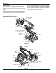
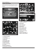
Controls and Indicators Controls and Indicators The operator shall know the location of each control and indicator and have a thorough knowledge of the function and operation of each before attempting to operate the machine. 32 34 30 18 31 20 25 28 23 21 29 22 24 26 27 19 1 33 Figure 2 –Battery Disconnect Switch 1. Battery disconnect switch Figure 4 – Upper Controls and Indicators 3 15 4 2 17 16 13 8 9 7 6 10 14 12 5 11 18. Emergency stop button 19. Drive joystick 20.
Pre-Operation Safety Inspection Pre-Operation Safety Inspection Note Carefully read, understand and follow all safety rules, operating instructions, labels and National Safety Instructions/Requirements. Perform the following steps each day before use. 1. Open the turntable covers and inspect for damage, fluid leaks or missing parts. 2. Check the level of the hydraulic fluid with the platform fully lowered. The fluid level must visible in the sight glass. Add recommended hydraulic fluid if necessary.
System Function Inspection System Function Inspection Refer to “Controls and Indicators” on page 6 for the locations of various controls and indicators. AWarning 5. Test each machine function (Jib, Riser, Platform Level, Platform Rotate, Lift, Slew, Telescope) from the lower control station by holding the ground operation switch up while operating the control toggle switches (ref: Figure 3 on page 6). STAND CLEAR of the work platform while performing the following checks. 6.
Operation Operation The aerial platform may be operated from either the lower or upper controls. ADanger The aerial platform is not electrically insulated. Death or serious injury will result from contact with, or inadequate clearance from, an energized conductor. Do not go closer than the minimum safe approach distance as defined by national safety regulations. Pinch points may exist between moving components.
Operation • If the drive fault light is flashing or not lit, repeat the previous steps to ensure the controls are set up properly. • After repeating the previous steps, if needed, and the drive fault light is still not a solid light remove the aerial platform from service until qualified maintenance personnel can make repairs. 5. Hold the appropriate toggle switch in the desired direction. 6. Release the function toggle switch to stop movement. 7.
Operation • Always look in the direction of movement as indicated by the directional arrows on the chassis. Use the following procedure to operate the drive and steer functions. 1. Determine the desired drive range for the specific driving conditions. Place the switch in the appropriate position to achieve the desired drive wheel operation. • Use high range (rabbit) when traveling across firm, flat, level surfaces. High range can only be activated when the booms are stowed.
Operation 5. Allow the fluid to drain from the line. 6. Lower the boom and close both connections. Emergency Lowering AWarning If the platform should fail to lower, NEVER climb down the elevating assembly. 3. Hold the emergency power switch in the emergency power position. 4. Hold the appropriate function toggle switch in the desired direction. After Use Each Day 1. Ensure that the platform is fully lowered. Stand clear of the elevating assembly while operating the Emergency Power System. 2.
Transporting the Machine Transporting the Machine Preparing for Transportation Use the following procedure to prepare the aerial platform for transportation. 1. Remove any unnecessary tools, materials, or other loose objects from the platform. 2. Close and latch the battery trays and cowling doors. By Crane ADanger Lifting by Crane is for transport purposes only. Stand clear of the machine when lifting.
Maintenance Maintenance AWarning Always block the elevating assembly whenever it is necessary to perform maintenance while the platform is elevated. Hydraulic Fluid The hydraulic fluid reservoir is located in the drive control compartment. Refer to Figure 6. • Check the battery fluid level daily, especially if the machine is being used in a warm, dry climate. • If electrolyte level is lower than 6 mm (¼″) above the plates add distilled water only.
Inspection and Maintenance Schedule 7. Visually inspect the battery charge indicator for proper charging rate. • The charger will turn on three to five seconds after a complete electrical connection is made. • As the batteries become charged, the indicator light for each level of charge will blink until its level is reached and then it will remain lit. • When the batteries are fully charged, all three lights on the battery charge indicator will be lit. 8.
Daily Preventative Maintenance Checklist Daily Preventative Maintenance Checklist Preventative Maintenance Report Date: Serial No: Owner: Serviced By: Model No: ITEM INSPECTION OR SERVICES Operator’s Manual In place, all pages readable and intact Y N R Electrical System Batteries Condition and charged for proper operation Battery fluid level and terminals Proper level/clean, connectors tight Battery charger and condition indicator Proper operation Cables and wiring harness No wear or phys
Specifications Specifications Aerial Platform Working height Maximum platform height Up and over height Maximum horizontal reach Main boom Articulation Extension Jib Articulation Extension Tail swing Turntable rotation Turning radius Inside Outside Wheelbase Ground clearance Maximum wheel load Maximum ground pressure Weight, EVW Approximate Width Stowed length Stowed height Platform Dimensions Toeboard height 52′ 4″ (15.9 m) 46′ 4″ (14.1 m) 25′ 2″ (7.6 m) 24′ 6″ (7.
Local Distributor: UpRight Powered Access HQ Vigo Centre Birtley Road Washington Tyne & Wear NE38 9DA Tel: +44 (0) 845 1550 057 Fax: +44 (0) 845 1557 756 http://www.upright.