
Manual
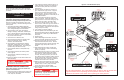
Starting the engine
From the lower controls
1. Turn the chassis key switch to chassis position.
2. Press the start button to crank the engine.
Release when the engine starts.
3. When the engine is cold: press and hold the
choke button while starting gasoline / propane
engines; press and hold the glow plug button for
six seconds prior to starting diesel engines.
From the platform controls
1. Turn the chassis key switch to platform controls.
2. Turn the platform keyswitch fully clockwise to
crank the engine. Release when engine starts.
3. When the engine is cold: Press and hold the
choke button while starting gasoline / propane
engines. Press and hold the glow plug button for
six seconds prior to starting the diesel engine.
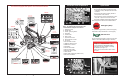
Driving
With Boom Lowered
1.
Turn chassis key switch to platform, and turn on (turn
clockwise) the chassis emergency stop switch.
2. Mount the platform, close and latch the gate.
3. Attach approved fall restraint to designated
platform anchorage point. Attach only one fall
restraint to each point.
4. Start engine.
5. Check that the area around and above the work
platform is clear of obstructions, holes, drop-offs,
persons in the route of travel, and the surface is
capable of supporting wheel loads.
6. Depress the foot switch and move the drive
control handle forward to travel forward and
reverse to travel in the reverse direction.
7. While driving, press the differential lock button,
located on the front of the drive control handle,
as necessary for improved traction.
Note: When the boom is rotated to the front of
the chassis (steering wheels aft) directions of
travel and steering will be reversed. Observe the
color coded arrows on the control panel near the
drive control handle, and on the chassis. They
will indicate the direction of travel when the drive
control handle is moved.
With Boom Elevated
Travel with boom elevated is restricted to firm
level surfaces only.
When driving elevated, the machine will travel at
creep speed (1/2 foot [.15 m] per second).
Steering
1. While depressing the foot switch, push the steer-
ing switch (located on top of the control handle) to
the left to turn left, and right to turn right.
Note: Steering is not self centering. Wheels
must be returned to the straight ahead position
by operating the steering switch.
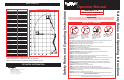
POSITIONING THE PLATFORM
Positioning the platform as close as possible to the
work area requires some planning. First, you must
survey the work site to find a suitable place to park
the machine. This must be a firm level area as
close as possible to the work area. Take into
consideration all obstructions on the ground and
overhead and avoid them.
Once you have moved the machine to a firm level
surface as near as possible to the work area, follow
the instructions on page five to position the platform
as close to the work area as possible.
Always, before operating any function, check the
area around and overhead for any obstructions or
electrical conductors.
NEVER exit the platform while the boom is
elevated. Keep both feet firmly planted on
the platform floor at all times.
Multifunction Controls
The UpRight AB-46 employs the use of multifunction
controls. This means that riser or boom extension
will function at full speed while simultaneously
operating upper boom, jib, turret, or rotating the
platform.
The turret may be rotated while driving if necessary
to make turns in tight areas. All other boom func-
tions will not operate while driving.
Lower Control Operation
All boom functions will operate at fixed speed.
1. Turn chassis keyswitch to chassis controls.
2. With engine running, operate boom control
switches to position the platform.
Routine Service Table Key
Interval
Daily=each shift (every day) or every eight hours
30
D
=every month (30 days) or every 50 hours
3
M
=every 3 months or 125 hours
6
M
=every 6 months or 250 hours
1
Y
=every year or 500 hours
2
Y
=every 2 years or 1000 hours
Y=Yes/Acceptable
N=No/Not Acceptable
R=Repaired/Acceptable
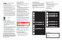
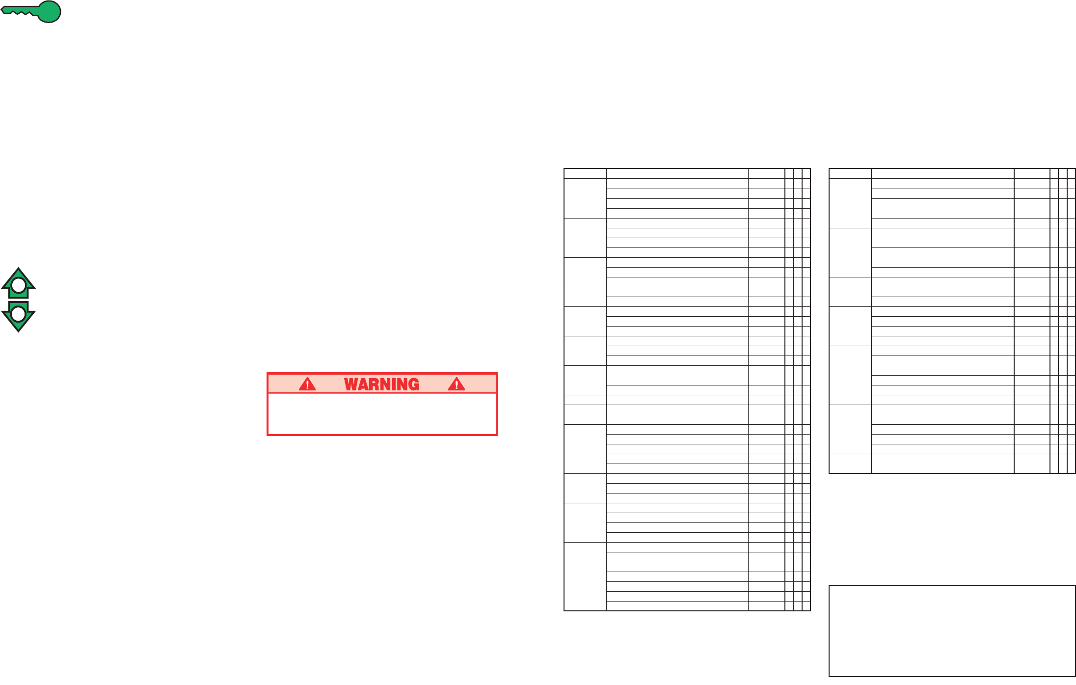
Routine Service Table
Service Report
Date: _______________
Owner: _________________________________
Model No: ____________ Serial No: __________
Serviced By: _____________________________
Service Interval: __________________________
COMPONENT INSPECTION OR SERVICES INTERVAL Y N R
Elevating Inspect for structural cracks Daily
Assembly Check pivot points for wear 30
D
Check pivot pin retaining bolts 30
D
for proper torque
Check members for deformation Daily
Chassis Check hoses for pinch or Daily
rubbing points
Check component mounting 6
M
for proper torque
Check welds for cracks Daily
Turret Check ring gear for proper lubrication and wear Daily
Lubricate worm gear bearings 150
H
/3
M
Lubricate ring gear (MoS
2
grease) 150
H
/3
M
Torque Check for leaks Daily
Hubs Check oil level 250
H
/6
M
Change oil after break-in period 50
H
/30
D
Change oil (SAE 90 wt. gear oil) 2000
H
/2
Y
Lift Check the cylinder rods for wear 30
D
Cylinders Check pivot pin retaining bolts 30
D
for proper torque
Check seals for leaks 30
D
Inspect pivot points for wear 30
D
Check fittings for proper torque 30
D
Entire Check for and repair Daily
Unit collision damage
Check fasteners for proper torque 3
M
Check for corrosion, remove and repaint 3
M
Lubricate 30
D
Labels Check for peeling, missing, or unreadable Daily
labels & replace
ROUTINE SERVICE
Use the following table as a guide for routine main-
tenance. Inspection and maintenance shall be
performed by personnel who are trained and
familiar with mechanical and electrical proce-
dures. Refer to the Service Manual for complete
service instructions.
Please copy this page and use the Routine Service
Table as a checklist when inspecting a machine for
service.
COMPONENT INSPECTION OR SERVICES INTERVAL Y N R
Engine Oil Check level and condition Daily
Check for leaks Daily
Change oil & filter (Dual Fuel) 3
M
Change oil & filter (Diesel) 100
HOURS
Engine Fuel Check fuel level Daily
System Check for leaks Daily
Replace fuel filter 6
M
Check air cleaner Daily
Battery Check electrolyte level Daily
Clean exterior 3
M
Clean terminals 3
M
Engine Check coolant level (with engine cold) Daily
Coolant Replace coolant 3
M
Hydraulic Check oil level Daily
Oil Change filter 6
M
Drain and replace with ISO 46 compatible oil 2
Y
Hydraulic Check for leaks Daily
System Check hose connections 30
D
Check hoses for exterior wear 30
D
Emergency Check operation of emergency override Daily
Hydraulic valves and hand pump
System Check operation of brake release hand pump Daily
Controller Check operation of all controls Daily
Control Check the exterior of the cable Daily
Cable for pinching, binding or wear
Platform Check fasteners for proper torque Daily
Floor and Check welds for cracks Daily
Rails Check condition of platform Daily
Check condition of anchorage points Daily
Check condition of operators manual Daily
Tires Check for damage Daily
Check air pressure (65 psi) Daily
Check lug nuts (torque to 90 ft. lbs. [123 Nm]) 30
D
Hydraulic Wipe clean 30
D
Pump Check for leaks at mating surfaces 30
D
Check for hose fitting leaks Daily
Check mounting bolts for proper torque 30
D
Hydraulic Check hydraulic drive motor operation Daily
Drive System
Check hoses, fittings, and valve block for leaks Daily
Steering Check fittings for proper torque 6
M
System Oil all pivot points 30
D
Check steering cylinder for leaks 30
D
Check linkage for wear areas 30
D
Check for missing / loose retainers Daily
4
9