AB38 Operator Manual This first section of the Operator manual is the English language version. Manuel Utilisateur èLa troisième section de ce manuel est la version en langue Française. Manual del Usuario El apartado cuarto de este manual del usuario corresponde a la versión en Españo. (EN) Manual part number 500423-106 for serial numbers 3700 to current. (FR) Manuel Pièce numéro 500423-106 pour numéro série 3700 jusqu'au numéro courant.
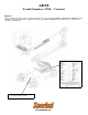
AB38 Serial Numbers 3700 – Current ENGLISH When contacting Snorkel for service or parts information, be sure to include the MODEL and SERIAL NUMBERS from the equipment nameplate. Should the nameplate be missing, the SERIAL NUMBER is also stamped on top of the chassis above the front axle pivot. Nameplate location Serial number stamped on floor of chassis beneath the steering cylinder. www.upright.
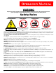
OPERATION MANUAL WARNING All personnel shall carefully read, understand and follow all safety rules and operating instructions before operating or performing maintenance on any Snorkel aerial work platform. Safety Rules Electrocution Hazard Tip Over Hazard Collision Hazard Fall Hazard A 83B g t h iRp U THIS MACHINE IS NOT INSULATED! NEVER elevate the platform or drive the machine while elevated unless the machine is on a firm, level surface.
C ONTENTS Safety Rules . . . . . . . . . . . . . . . . . . . . . . . . . . . . . . . . . . . . . . . . . . . . . . . . . . . . . . . . . . . . . . . . . . . . Page 1 Introduction & General Description. . . . . . . . . . . . . . . . . . . . . . . . . . . . . . . . . . . . . . . . . . . . . . . . . Page 3 Special Limitations . . . . . . . . . . . . . . . . . . . . . . . . . . . . . . . . . . . . . . . . . . . . . . . . . . . . . . . . . . . . . . Page 4 Controls & Indicators . . . . . . . . . . . . . . . . .
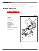
Introduction I NTRODUCTION This manual covers the AB38N and the AB38W Aerial Work Platforms. This manual must be stored on the machine at all times. Read, understand and follow all safety rules and operating instructions before attempting to operate the machine. G ENERAL D ESCRIPTION ! W A R N I N G ! DO NOT use the maintenance platform without guardrails properly assembled and in place. Figure 1: AB38 1. Platform 2. Entry Bar 2 3. Elevating Assembly 1 4 5 3 4. Platform Controls 6 5.
Special Limitations S PECIAL L IMITATIONS Travel with the platform raised is limited to creep speed range. Elevating the platform is limited to firm, level surfaces only. ! D A N G E R ! The elevating function shall ONLY be used when the work platform is level and on a firm surface. The work platform is NOT intended to be driven over uneven, rough, or soft terrain. PLATFORM CAPACITY Two people and tools may occupy the platform.
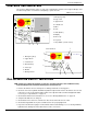
Controls and Indicators C ONTROLS AND I NDICATORS The operator shall know the location of each control and indicator and have a thorough knowledge of the function and operation of each before attempting to operate the unit. Figure 2: Controls and Indicators Upper Controls 1. Emergency Stop 1 2. Cage Level 3. Upper Boom 11 4. Lower Boom 10 2 5. Drive 9 3 6. Horn 7. Slew (Rotate) 4 8. Display 5 9. Telescope 10. Joystick 11. Key Switch (on side of box) 6 7 8 7 Lower Controls 1 1.
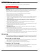
System Function Inspection S YSTEM F UNCTION I NSPECTION Refer to Figure 1 and Figure 2 for the locations of various controls and indicators. ! W A R N I N G ! STAND CLEAR of the work platform while performing the following checks. Before operating the machine, survey the work area for surface hazards such as holes, drop-offs, bumps and debris. Check in ALL directions, including above the work platform, for obstructions and electrical conductors.
Operation ROTATING THE PLATFORM 1. Select the rotate function button (the button will illuminate to confirm selection). 2. While engaging the Interlock Switch, move the Control Handle forwards or backwards to achieve clockwise or counter clockwise rotation. 3. If the machine is not level the tilt alarm will sound and the machine will not rotate. OPERATING THE TE L E S C O P E 1. Select telescope function button (the button will illuminate to confirm selection). 2.
Transporting the Machine TRANSPORTING THE M ACHINE BY CRANE Secure the straps to chassis lifting/tie down points only. BY FORKLIFT ! D A N G E R ! Forklifting and Lifting by Crane are for transport only. See specifications for weight of machine and be certain that forklift is of adequate capacity to lift the machine. Figure 4: Transporting the Machine Forklift from the side by lifting under the Chassis. B Y TR U C K 1. Maneuver the machine into transport position and chock wheels. 2.
Maintenance M AINTENANCE ! W A R N I N G ! Never perform service while the platform is elevated. HYDRAULIC FLUID The hydraulic fluid reservoir is located in the chassis door. Figure 5: Hydraulic Fluid Reservoir and Dipstick NOTE: Never add fluid if the platform is elevated. CHECK HYDRAULIC FLUID 1. Make sure that the platform is fully lowered. 2. Open the chassis door. 3. Remove the filler cap from the hydraulic fluid reservoir. Filler Cap 4. Check the fluid level on the dipstick on the filler cap.
Maintenance BATTER Y MAINTENANCE Figure 6: Access to Batteries ! W A R N I N G ! Hazard of explosive gas mixture. Keep sparks, flame, and smoking material away from batteries. Always wear safety glasses when working near batteries. Battery fluid is highly corrosive. Thoroughly rinse away any spilled fluid with clean water. Always replace batteries with Snorkel batteries or manufacturer approved replacements weighing 26,3 kg (58 lbs.) each.
Inspection and Maintenance Schedule I NSPECTION AND M AINTENANCE S CHEDULE The Complete Inspection consists of periodic visual and operational checks, along with periodic minor adjustments that assure proper performance. Daily inspection will prevent abnormal wear and prolong the life of all systems. The inspection and maintenance schedule should be performed at the specified intervals.
Daily Preventative Maintenance Checklist D AILY P REVENTATIVE M AINTENANCE C HECKLIST MAINTENANCE TABLE KEY PREVENTATIVE MAINTENANCE REPORT Y = Yes/Acceptable Date: _______________________________________ N = No/Not Acceptable Owner: ______________________________________ R = Repaired/Acceptable Model No: ___________________________________ Serial No:____________________________________ Serviced By: ___________________________________________ COMPONENT Battery Chassis Control Cable Controller Drive
Decal Location D ECAL L OCATION ITEM 1 2 3 4 5 6 7 8 12 13 14 16 17 18 19 20 21 22 23 24 25 26 27 28 29 30 31 32 33 34 35 Operation Manual PART NO.
Specifications S PECIFICATIONS Table 1-1 : Specifications ITEM Duty Cycle Platform Size Max. Platform Capacity CE Version ANSI Version Max. Number of Occupants Height Maximum Working Height Maximum Platform Height Min. Platform Floor Height Max.
AB38 Numéros de série 3700 – actuel FRANÇAIS En cas de contact avec Snorkel pour obtenir des renseignements sur les réparations ou les pièces, indiquer les NUMÉROS de MODÈLE et de SÉRIE figurant sur la plaque signalétique de la machine. En cas d'absence de plaque signalétique, le NUMÉRO DE SÉRIE est également estampé sur le dessus du châssis, au-dessus du pivot d'essieu avant.
GUIDE DE L'OPÉRATEUR AVERTISSEMENT Tout le personnel devra lire soigneusement, comprendre et respecter toutes les règles de sécurité et instructions d'utilisation avant d'utiliser ou d'effectuer des travaux de maintenance sur une plate-forme de travail aérien Snorkel.
TABLE DES MATIÈRES Utilisation Règles de sécurité. . . . . . . . . . . . . . . . . . . . . . . . . . . . . . . . . . . . . . . . . . . . . . . . . . . . . . . . . . . . . . . Page 1 Introduction & Description générale . . . . . . . . . . . . . . . . . . . . . . . . . . . . . . . . . . . . . . . . . . . . . . . . Page 3 Restrictions spéciales . . . . . . . . . . . . . . . . . . . . . . . . . . . . . . . . . . . . . . . . . . . . . . . . . . . . . . . . . . . Page 4 Commandes & indicateurs . . . . . . . . .
Introduction I NTRODUCTION Le présent manuel couvre la plate-forme de travail aérien AB38N/W. Il doit être rangé sur la machine en permanence. Il est indispensable de lire, comprendre et respecter toutes les règles de sécurité et instructions d'utilisation avant d'essayer d'utiliser la machine. D ESCRIPTION GÉNÉRALE Figure 1 : AB38 1. Plate-forme ! AV E RT I S S E M E N T 2 ! 1 4 5 3 NE PAS utiliser la plate-forme de maintenance sans les garde-corps correctement montés et en place 6 2.
Restrictions spéciales R ESTRICTIONS SPÉCIALES Tout déplacement avec la plate-forme levée est limitée à la gamme de vitesses très lentes. L'élévation de la plate-forme est limitée uniquement aux surfaces fermes et de niveau. ! D A N G E R ! La fonction d'élévation sera utilisée SEULEMENT quand la plate-forme de travail est de niveau et sur une surface ferme. La plate-forme de travail N'EST PAS CONÇUE pour être conduite sur un terrain inégal, non nivelé ou mou.
Commandes et indicateurs C OMMANDES ET INDICATEURS L'opérateur doit connaître l'emplacement de chaque commande et indicateur et avoir une connaissance approfondie de la fonction et de l'utilisation de tous avant d'essayer d'utiliser la machine. Figure 2 : Commandes et indicateurs Commandes supérieures 1. Arrêt d'urgence 1 2. Niveau de la plate-forme 3. Flèche supérieure 11 4. Flèche inférieure 10 2 5. Déplacement 9 3 6. Avertisseur sonore 7. Pivotement (Rotation) 4 8. Affichage 5 9.
Vérification des fonctions du système VÉRIFICATION DES FONCTIONS DU SYSTÈME Se référer à la Figure 1 et la Figure 2 pour les emplacements des commandes et indicateurs. ! AV E RT I S S E M E N T ! SE TENIR À L'ÉCART de la plate-forme de travail pour effectuer les vérifications suivantes. Avant d'utiliser la machine, contrôler sur la surface de travail l'absence de trous, dénivellations, bosses et débris.
Utilisation ROTATION DE LA PLATE-FORME 1. Sélectionner le bouton de fonction de rotation (le bouton s'allume pour confirmer la sélection). 2. Tout en engageant le commutateur de verrouillage, déplacer la poignée de commande vers l'avant ou l'arrière pour obtenir une rotation dans le sens des aiguilles d'une montre ou dans le sens inverse. 3. Si la machine n'est pas de niveau, l'alarme d'inclinaison retentit et la plate-forme ne tourne pas. UTILISATION DE LA FLÈCHE TÉLESCOPIQUE 1.
Transport de la machine TRANSPORT DE LA MACHINE PAR GRUE Fixer les sangles uniquement aux points de levage/arrimage du châssis. PAR ! CHARIOT ÉLÉVATEUR À FOURCHE D A N G E R ! Le levage par chariot à fourche et par grue sont pour le transport seulement. Voir les spécifications pour le poids de la machine et vérifier que le chariot élévateur à fourche a une capacité suffisante pour soulever la machine.
Maintenance M AINTENANCE ! AV E RT I S S E M E N T ! Ne jamais réparer le véhicule alors que la plate-forme est montée. LIQUIDE HYDRAULIQUE Le réservoir de liquide hydraulique est situé dans la porte du châssis. Figure 5 : Réservoir de liquide hydraulique et jauge NOTE : Ne jamais ajouter de liquide si la plate-forme est montée. VÉRIFICATION DU LIQUIDE HYDRAULIQUE 1. S'assurer que la plate-forme est complètement abaissée. 2. Ouvrir la porte du châssis. 3.
Maintenance MAINTENANCE DES BATTERIES Figure 6 : Accès aux batteries ! AV E RT I S S E M E N T ! Risque de mélange de gaz explosif. Maintenir les étincelles, flammes et cigarettes à l'écart des batteries. Toujours porter des lunettes de sécurité pour travailler près des batteries. Le liquide des batteries est hautement corrosif. Rincer soigneusement tout déversement de liquide avec de l'eau propre.
Programme d'inspection et de maintenance P ROGRAMME D ' INSPECTION ET DE MAINTENANCE L'inspection complète se compose de vérifications visuelles et opérationnelles périodiques, associées à des réglages périodiques mineurs assurant un fonctionnement correct. Une inspection quotidienne évitera toute usure anormale et prolongera la durée de vie de tous les systèmes. Le programme d'inspection et de maintenance doit être exécuté aux intervalles indiqués.
Liste de vérification quotidienne de maintenance préventive L ISTE DE VÉRIFICATION QUOTIDIENNE DE MAINTENANCE PRÉVENTIVE LÉGENDE DU TABLEAU DE MAINTENANCE RAPPORT DE MAINTENANCE PRÉVENTIVE O = Oui/Acceptable Date : _______________________________________ N = Non/Inacceptable Propriétaire : _________________________________ R = Réparé/Acceptable N° de modèle :________________________________ N° de série :__________________________________ Entretenu par :________________________________ ___________
Étiquettes É TIQUETTES ITEM 1 2 3 4 5 6 7 8 12 13 14 16 17 18 19 20 21 22 23 24 25 26 27 28 29 30 31 32 33 34 35 PART NO.
Spécifications S PÉCIFICATIONS Table 1-1 : Specifications ITEM Duty Cycle Platform Size Max. Platform Capacity CE Version ANSI Version Max. Num ber of Occupants Height Maximum Working Height Maximum Platf orm Height Min. Platf orm Floor Height Max.
AB38 Números de serie 3700 – Actual ESPAÑOL Cuando se ponga en contacto con Snorkel pasa solicitar asistencia o información sobre repuestos, incluya siempre el MODELO y NÚMEROS DE SERIE que figuran en la placa de identificación del equipo. Si esta placa se perdiera, el NÚMERO DE SERIE se encuentra también impreso en la parte superior del chasis, sobre el pivote del eje delantero. La placa de identificación del equipo. Número de serie impreso en el suelo del chasis por debajo del cilindro de dirección.
MANUAL DE FUNCIONAMIENTO ADVERTENCIA El personal debe leer atentamente, comprender y respetar todas las reglas de seguridad e instrucciones de funcionamiento antes de utilizar o realizar operaciones de mantenimiento en cualquier plataforma aérea de trabajo de Snorkel. Reglas de seguridad Riesgo de volcado ESTA MÁQUINA NO ESTÁ PROTEGIDA. PELIGRO DE ELECTROCUCIÓN. NO eleve nunca la plataforma ni conduzca con ella elevada en una superficie que no esté firme y nivelada.
Í NDICE Funcionamiento Reglas de seguridad . . . . . . . . . . . . . . . . . . . . . . . . . . . . . . . . . . . . . . . . . . . . . . . . . . . . . . . . . . . . Página 1 Introducción y descripción general. . . . . . . . . . . . . . . . . . . . . . . . . . . . . . . . . . . . . . . . . . . . . . . . Página 3 Limitaciones especiales . . . . . . . . . . . . . . . . . . . . . . . . . . . . . . . . . . . . . . . . . . . . . . . . . . . . . . . . . Página 4 Controles e indicadores . . . . . . . . . . . . . . .
Introducción I NTRODUCCIÓN Este es el manual de la plataforma aérea de trabajo AB38. El manual se deberá llevar siempre en la máquina. Lea, comprenda y respete las reglas de seguridad y las instrucciones de funcionamiento antes de comenzar a utilizar la máquina. D ESCRIPCIÓN GENERAL ! ADVERTENCIA ! NO utilice la plataforma de mantenimiento sin que la barandilla se encuentre correctamente fijada en su sitio Figure 1: AB38 1. Plataforma 2. Barra de entrada 2 3. Conjunto de elevación 1 4 5 3 4.
Limitaciones especiales L IMITACIONES ESPECIALES El desplazamiento con la plataforma elevada está limitado al rango de velocidad de arrastre. La elevación de la plataforma únicamente se podrá llevar a cabo en superficies firmes y niveladas. ! P E L I G R O ! La función de elevación ÚNICAMENTE se utilizará cuando la plataforma de trabajo esté nivelada y situada sobre una superficie firme. La plataforma de trabajo NO está preparada para utilizarla sobre un terreno irregular, en mal estado o inestable.
Controles e indicadores C ONTROLES E INDICADORES El operario debe conocer a fondo la ubicación de todos los controles e indicadores, así como la función y el funcionamiento de cada uno de ellos antes de comenzar a utilizar la unidad. Figure 2: Controles e indicadores Controles superiores 1. Parada de emergencia 1 2. Nivelación de la jaula 3. Pluma superior 11 4. Pluma inferior 10 2 5. Transmisión 9 3 6. Bocina 7. Giro del carro (Rotación) 4 8. Pantalla 5 9. Telescopio 10.
Inspección de la función del sistema I NSPECCIÓN DE LA FUNCIÓN DEL SISTEMA Consulte Figura 1 y Figura 2 para conocer la ubicación de los distintos controles e indicadores. ! ADVERTENCIA ! ALÉJESE de la plataforma de trabajo mientras se llevan a cabo las siguientes comprobaciones. Antes de utilizar la máquina examine la superficie de trabajo en busca de riesgos en la superficie, como por ejemplo hoyos, desniveles, baches o escombros.
Funcionamiento ROTACIÓN DE LA PLATAFORMA 1. Seleccione el botón de la función de rotación (el botón se iluminará para confirmar la selección). 2. Mientras acciona el interruptor de bloqueo, empuje hacia adelante o tire hacia atrás el mango de control hasta conseguir una rotación en el sentido de las agujas del reloj o en el opuesto. 3. Si la máquina no está nivelada, sonará la alarma de inclinación y no podrá rotar. FUNCIONAMIENTO DEL TELESCOPIO 1.
Transporte de la máquina TRANSPORTE DE LA MÁQUINA CON UNA GRúA Fije las correas únicamente a los puntos de elevación/alineación del chasis. CON ! HORQUILLA ELEVADORA P E L I G R O ! La elevación mediante horquilla elevadora o grúa se lleva a cabo únicamente para el transporte. Consulte las especificaciones del peso de la máquina y asegúrese de que la horquilla cuenta con una capacidad adecuada para elevar la máquina.
Mantenimiento M ANTENIMIENTO ! ADVERTENCIA ! Nunca realice labores de mantenimiento cuando la plataforma esté elevada. LÍQUIDO HIDRÁULICO El depósito de líquido hidráulico está ubicado en la puerta del chasis. Figure 5: Depósito de líquido hidráulico y varilla de medición NOTA: Nunca añada líquido cuando la plataforma esté elevada. COMPRUEBE EL LÍQUIDO HIDRÁULICO 1. Asegúrese de que la plataforma está bajada por completo. 2. Abra la puerta del chasis. 3.
Mantenimiento MANTENIMIENTO DE LA BATERÍA Figure 6: Acceso a las baterías ! ADVERTENCIA ! Riesgo de mezcla de gas explosivo. Aleje las baterías de chispas, llamas u otras fuentes de ignición. Utilice gafas de seguridad siempre que trabaje cerca de las baterías. El líquido de las baterías es extremadamente corrosivo. Enjuague cuidadosamente cualquier líquido derramado con agua limpia.
Plan de inspección y mantenimiento P LAN DE INSPECCIÓN Y MANTENIMIENTO La inspección completa consiste en una serie de comprobaciones visuales y de funcionamiento periódicas, además de ajustes periódicos de menor importancia para garantizar un rendimiento adecuado. Las inspecciones diarias evitarán un desgaste anormal y prolongarán la vida de todos los sistemas. El plan de inspección y mantenimiento se deberá llevar a cabo en los intervalos señalados.
Lista de control de mantenimiento preventivo diario L ISTA DE CONTROL DE MANTENIMIENTO PREVENTIVO DIARIO CLAVES INFORME DE LA TABLA DE MANTENIMIENTO DE MANTENIMIENTO PREVENTIVO S = Sí/Aceptable Fecha: ______________________________________ N = No/No aceptable Propietario: __________________________________ R = Reparado/Aceptable Núm. de modelo: ______________________________ Núm.
Etiqueta Etiqueta ITEM 1 2 3 4 5 6 7 8 12 13 14 16 17 18 19 20 21 22 23 24 25 26 27 28 29 30 31 32 33 34 35 Manual de funcionamiento PART NO.
Especificaciones E SPECIFICACIONES Table 1-1 : Specifications ITEM Duty Cycle Platform Size Max. Platform Capacity CE Version ANSI Version Max. Num ber of Occupants Height Maximum Working Height Maximum Platform Height Min. Platform Floor Height Max.
Local Distributor: Distributeur local: El Distribuidor local: Snorkel International Inc. P.O. Box 1160 St. Joseph, MO 64502-1160 USA TEL: + 1-800-255-0317 www.snorkelusa.