WARNING ! The AB38N Machine has been re-assessed to ensure compliance to the Machinery Directive (2006/42/EC). The Machine rating has been changed from: 2 People Indoors and Outdoors. To 2 People Indoors and 1 Person Outdoors.
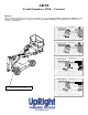
AB38 Serial Numbers 3700 – Current ENGLISH When contacting UpRight for service or parts information, be sure to include the MODEL and SERIAL NUMBERS from the equipment nameplate. Should the nameplate be missing, the SERIAL NUMBER is also stamped on top of the chassis above the front axle pivot. UpRight MODEL AB38W MAX. PLATFORM HEIGHT MAX. PLATFORM LOAD VIGO CENTRE WASHINGTON, TYNE & WEAR, UK. SERIAL No. 11.5m UNLADEN WEIGHT 400N MAX. LATERAL FORCE MAX. CHASSIS INCLINATION MAX.
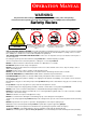
OPERATION MANUAL WARNING All personnel shall carefully read, understand and follow all safety rules and operating instructions before operating or performing maintenance on any UpRight aerial work platform. Safety Rules Electrocution Hazard Tip Over Hazard Collision Hazard Fall Hazard A 83B g t h iRp U THIS MACHINE IS NOT INSULATED! NEVER elevate the platform or drive the machine while elevated unless the machine is on a firm, level surface.
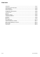
C ONTENTS Safety Rules . . . . . . . . . . . . . . . . . . . . . . . . . . . . . . . . . . . . . . . . . . . . . . . . . . . . . . . . . . . . . . . . . . . . Page 1 Introduction & General Description. . . . . . . . . . . . . . . . . . . . . . . . . . . . . . . . . . . . . . . . . . . . . . . . . Page 3 Special Limitations . . . . . . . . . . . . . . . . . . . . . . . . . . . . . . . . . . . . . . . . . . . . . . . . . . . . . . . . . . . . . . Page 4 Controls & Indicators . . . . . . . . . . . . . . . . .
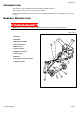
Introduction I NTRODUCTION This manual covers the AB38N and the AB38W Aerial Work Platforms. This manual must be stored on the machine at all times. Read, understand and follow all safety rules and operating instructions before attempting to operate the machine. G ENERAL D ESCRIPTION ! W A R N I N G ! DO NOT use the maintenance platform without guardrails properly assembled and in place. Figure 1: AB38 1. Platform 2. Entry Bar 2 3. Elevating Assembly 1 4 5 3 4. Platform Controls 6 5.
Special Limitations S PECIAL L IMITATIONS Travel with the platform raised is limited to creep speed range. Elevating the platform is limited to firm, level surfaces only. ! D A N G E R ! The elevating function shall ONLY be used when the work platform is level and on a firm surface. The work platform is NOT intended to be driven over uneven, rough, or soft terrain. PLATFORM CAPACITY Two people and tools may occupy the platform.
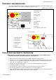
Controls and Indicators C ONTROLS AND I NDICATORS The operator shall know the location of each control and indicator and have a thorough knowledge of the function and operation of each before attempting to operate the unit. Figure 2: Controls and Indicators Upper Controls 1. Emergency Stop 1 2. Cage Level 3. Upper Boom 11 4. Lower Boom 10 2 5. Drive 9 3 6. Horn 7. Slew (Rotate) 4 8. Display 5 9. Telescope 10. Joystick 11. Key Switch (on side of box) 6 7 8 7 Lower Controls 1 1.
System Function Inspection S YSTEM F UNCTION I NSPECTION Refer to Figure 1 and Figure 2 for the locations of various controls and indicators. ! W A R N I N G ! STAND CLEAR of the work platform while performing the following checks. Before operating the machine, survey the work area for surface hazards such as holes, drop-offs, bumps and debris. Check in ALL directions, including above the work platform, for obstructions and electrical conductors.
Operation ROTATING THE PLATFORM 1. Select the rotate function button (the button will illuminate to confirm selection). 2. While engaging the Interlock Switch, move the Control Handle forwards or backwards to achieve clockwise or counter clockwise rotation. 3. If the machine is not level the tilt alarm will sound and the machine will not rotate. OPERATING THE TE L E S C O P E 1. Select telescope function button (the button will illuminate to confirm selection). 2.
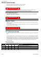
Transporting the Machine TRANSPORTING THE M ACHINE BY CRANE Secure the straps to chassis lifting/tie down points only. BY FORKLIFT ! D A N G E R ! Forklifting and Lifting by Crane are for transport only. See specifications for weight of machine and be certain that forklift is of adequate capacity to lift the machine. Figure 4: Transporting the Machine Forklift from the side by lifting under the Chassis. B Y TR U C K 1. Maneuver the machine into transport position and chock wheels. 2.
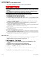
Maintenance M AINTENANCE ! W A R N I N G ! Never perform service while the platform is elevated. HYDRAULIC FLUID The hydraulic fluid reservoir is located in the chassis door. Figure 5: Hydraulic Fluid Reservoir and Dipstick NOTE: Never add fluid if the platform is elevated. CHECK HYDRAULIC FLUID 1. Make sure that the platform is fully lowered. 2. Open the chassis door. 3. Remove the filler cap from the hydraulic fluid reservoir. 4. Check the fluid level on the dipstick on the filler cap.
Maintenance BATTER Y MAINTENANCE Figure 6: Access to Batteries ! W A R N I N G ! Hazard of explosive gas mixture. Keep sparks, flame, and smoking material away from batteries. Always wear safety glasses when working near batteries. Battery fluid is highly corrosive. Thoroughly rinse away any spilled fluid with clean water. Always replace batteries with UpRight batteries or manufacturer approved replacements weighing 26,3 kg (58 lbs.) each.
Inspection and Maintenance Schedule I NSPECTION AND M AINTENANCE S CHEDULE The Complete Inspection consists of periodic visual and operational checks, along with periodic minor adjustments that assure proper performance. Daily inspection will prevent abnormal wear and prolong the life of all systems. The inspection and maintenance schedule should be performed at the specified intervals.
Daily Preventative Maintenance Checklist D AILY P REVENTATIVE M AINTENANCE C HECKLIST MAINTENANCE TABLE KEY PREVENTATIVE MAINTENANCE REPORT Y = Yes/Acceptable Date: _______________________________________ N = No/Not Acceptable Owner: ______________________________________ R = Repaired/Acceptable Model No: ___________________________________ Serial No:____________________________________ Serviced By: _________________________________ ___________________________________________ COMPONENT Battery Chas
Decal Location D ECAL L OCATION ITEM 1 2 3 4 5 6 7 8 9 10 11 12 13 14 15 16 17 18 19 20 21 Operation Manual PART NO.
Specifications S PECIFICATIONS Table 1-1 : Specifications ITEM Duty Cycle Platform Size Max. Platform Capacity CE Version ANSI Version Max. Number of Occupants Height Maximum Working Height Maximum Platform Height Min. Platform Floor Height Max.
Local Distributor: Lokaler Vertiebshändler: Distributeur local: El Distribuidor local: Il Distributore locale: USA Europe TEL: +1 (559) 443 6600 FAX: +1 (559) 268 2433 TEL: +44 (0) 845 1550 058 FAX: +44 (0) 195 2299 948 www.upright.