
Owner manual


Table Of Contents
- Chapter 1 – Introduction
- Aerial Platform Features
- Options
- Operator’s Manual
- Safety Alerts
- Operation
- Maintenance
- Manual of Responsibilities
- Additional Information
- Component Identification
- Working Envelope
- General Specifications
- Electrocution Hazards
- Minimum Safe Approach Distance
- Prestart Inspection
- Work Place Inspection and Practices
- Operation
- Tip-Over and Falling Hazards
- Electrical System
- Hydraulic System
- Placards and Decals
- Emergency Stop Controls
- Emergency Power System
- Ground Operation Switch
- Platform Foot Switch
- Guardrails
- Lanyard Anchors
- Tilt Alarm
- Ground Fault Circuit Interrupter
- Horn
- Drive Motion Alarm
- Lowering Alarm
- Flashing Light
- Hour Meter
- Battery Level Indicator
- Battery Charge Indicator
- Hydraulic Fluid Filter Gauge
- Fluid Level Sight Gauge
- General Maintenance
- Charging
- Battery Disconnect Switch
- Lower Controls
- Circuit Breaker Reset Buttons
- Upper Controls
- Operator’s Manual Holder
- Electrical System
- Cables and Wiring Harness
- Hydraulic System
- Tires and Wheels
- Lower Control Station
- Level Sensor
- Flashing Light
- Structures
- Upper Control Station
- Drive Motion Alarm
- Lowering Alarm
- Placards and Decals
- Prestart Inspection Checklist
- Cold Weather Start-Up
- Preparing for Operation
- Lower Controls
- Upper Controls
- Gradeability
- Electrical Power Outlet
- Air Line
- Stowing
- Transporting
- Emergency Power System
- Towing
- Troubleshooting Chart
- Table of Contents
- Introduction
- Component Identification
- Special Limitations
- Controls and Indicators
- Battery Disconnect Switch
- Lower Controls
- Circuit Breaker Reset Buttons
- Upper Controls
- Preheat Switch
- Start Switch
- Emergency Stop Button
- Drive Joystick
- Steer Switch
- Drive Range Switch
- Boom Speed Knob
- Rotation Switch
- Riser Switch
- Boom Elevation Switch
- Boom Extension Switch
- Jib Articulation Switch
- Platform Level Switch
- Platform Rotation Switch
- Engine/Emergency Power Switch
- Horn Switch
- Platform Foot Switch
- AC Generator Switch
- Hydraulic Oil Warm-Up Switch
- Pre-Operation Safety Inspection
- System Function Inspection
- Operation
- Cold Weather Start-Up
- Hydraulic System Cold Weather Warm-Up
- Hydraulic System Warm-Up Switch
- Manually Warming The Hydraulic System
- Preparing for Operation
- Lower Controls
- Upper Controls
- Boom Operation
- Driving and Steering
- Drive Speeds
- Pivoting Front Axle
- All Motion Alarm
- Electrical Power Outlet
- AC Generator
- Air Line
- Emergency Lowering
- Lower Controls
- Upper Controls
- After Use Each Day
- Transporting the Machine
- Maintenance
- Inspection and Maintenance Schedule
- Daily Preventative Maintenance Checklist
- Specifications
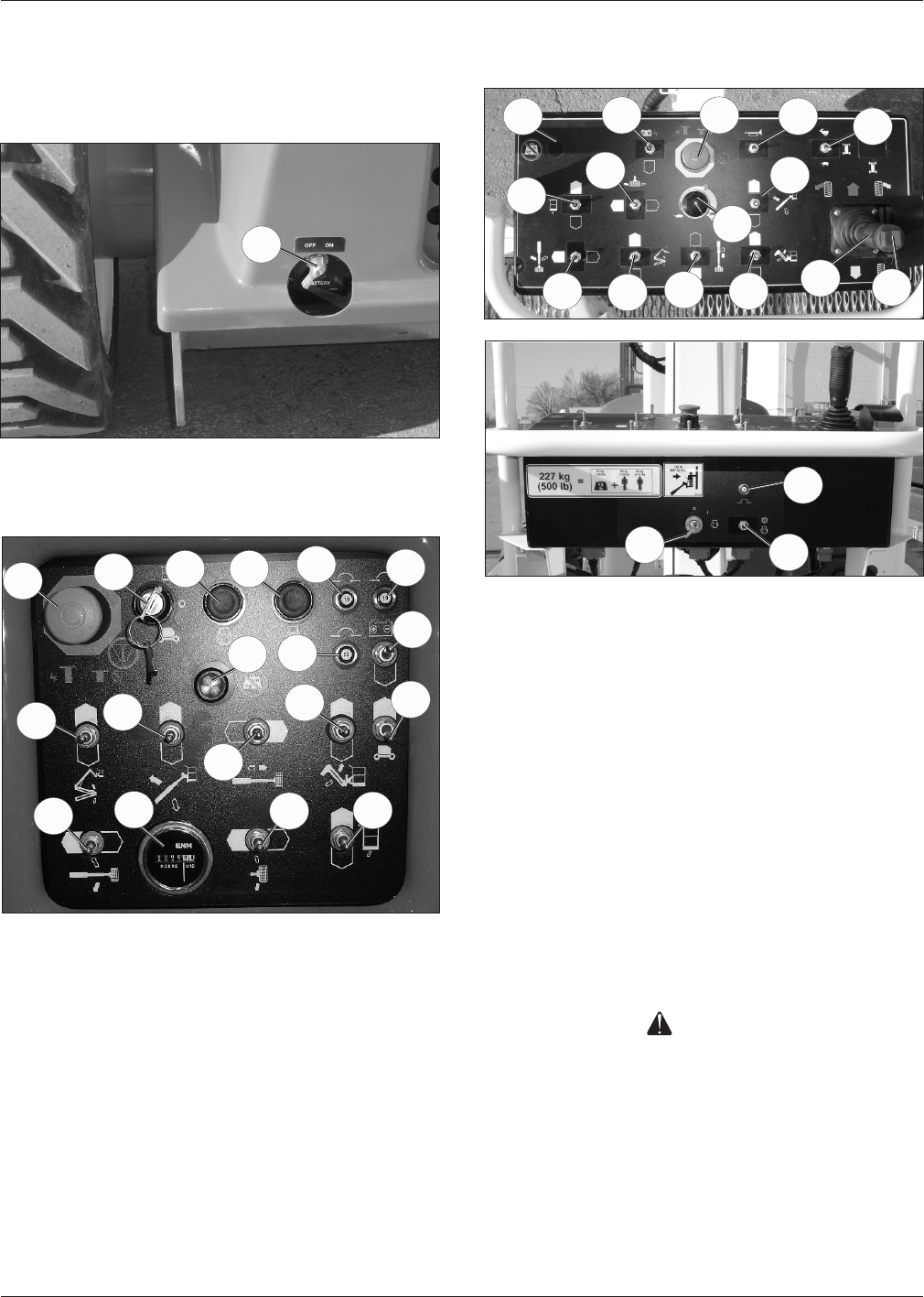
Controls and Indicators
6 A46JRT – 0260228
18. Main control circuit breaker
19. Platform overload light
Figure 4 – Upper Controls and Indicators
20. Preheat switch
21. Start switch
22. Emergency stop button
23. Drive joystick
24. Steer switch
25. Drive range switch
26. Boom speed knob
27. Rotation switch
28. Riser switch
29. Boom elevation switch
30. Boom extension switch
31. Jib articulation switch
32. Platform level switch
33. Platform rotation switch
34. Engine/Emergency power switch
35. Horn
36. Upper control circuit breaker
37. Platform overload light
Danger
Pinch points may exist between moving components.
Death or serious injury will result from becoming
trapped between components, buildings, structures,
or other obstacles. Make sure all personnel stand
clear while operating the aerial platform.
Controls to position the platform are located on the
lower control panel on the turntable and on the upper
control panel in the platform.
Controls to drive the aerial platform are located on the
upper control panel only.
•
•
Controls and Indicators
The operator shall know the location of each control and
indicator and have a thorough knowledge of the function
and operation of each before attempting to operate the
machine.
Figure 2 – Battery Disconnect Switch
1. Battery disconnect switch
Figure 3 – Lower Controls and Indicators
2. Preheat button
3. Start button
4. Emergency stop button
5. Controls selector switch
6. Ground operation switch
7. Rotation switch
8. Riser switch
9. Boom elevation switch
10. Boom extension switch
11. Jib articulation switch
12. Platform level switch
13. Platform rotation switch
14. Engine/emergency power switch
15. Hour meter
16. Relays circuit breaker
17. Switches circuit breaker
1
3
4
5
2
6
7
8
9
11
12
13
14
15
17
18
16
10
19
28
29
30
31
32
33
24
25
26
27
23
35
2234
37
20
21
36