
Owner manual


Table Of Contents
- Chapter 1 – Introduction
- Aerial Platform Features
- Options
- Operator’s Manual
- Safety Alerts
- Operation
- Maintenance
- Manual of Responsibilities
- Additional Information
- Component Identification
- Working Envelope
- General Specifications
- Electrocution Hazards
- Minimum Safe Approach Distance
- Prestart Inspection
- Work Place Inspection and Practices
- Operation
- Tip-Over and Falling Hazards
- Electrical System
- Hydraulic System
- Placards and Decals
- Emergency Stop Controls
- Emergency Power System
- Ground Operation Switch
- Platform Foot Switch
- Guardrails
- Lanyard Anchors
- Tilt Alarm
- Ground Fault Circuit Interrupter
- Horn
- Drive Motion Alarm
- Lowering Alarm
- Flashing Light
- Hour Meter
- Battery Level Indicator
- Battery Charge Indicator
- Hydraulic Fluid Filter Gauge
- Fluid Level Sight Gauge
- General Maintenance
- Charging
- Battery Disconnect Switch
- Lower Controls
- Circuit Breaker Reset Buttons
- Upper Controls
- Operator’s Manual Holder
- Electrical System
- Cables and Wiring Harness
- Hydraulic System
- Tires and Wheels
- Lower Control Station
- Level Sensor
- Flashing Light
- Structures
- Upper Control Station
- Drive Motion Alarm
- Lowering Alarm
- Placards and Decals
- Prestart Inspection Checklist
- Cold Weather Start-Up
- Preparing for Operation
- Lower Controls
- Upper Controls
- Gradeability
- Electrical Power Outlet
- Air Line
- Stowing
- Transporting
- Emergency Power System
- Towing
- Troubleshooting Chart
- Table of Contents
- Introduction
- Component Identification
- Special Limitations
- Controls and Indicators
- Battery Disconnect Switch
- Lower Controls
- Circuit Breaker Reset Buttons
- Upper Controls
- Preheat Switch
- Start Switch
- Emergency Stop Button
- Drive Joystick
- Steer Switch
- Drive Range Switch
- Boom Speed Knob
- Rotation Switch
- Riser Switch
- Boom Elevation Switch
- Boom Extension Switch
- Jib Articulation Switch
- Platform Level Switch
- Platform Rotation Switch
- Engine/Emergency Power Switch
- Horn Switch
- Platform Foot Switch
- AC Generator Switch
- Hydraulic Oil Warm-Up Switch
- Pre-Operation Safety Inspection
- System Function Inspection
- Operation
- Cold Weather Start-Up
- Hydraulic System Cold Weather Warm-Up
- Hydraulic System Warm-Up Switch
- Manually Warming The Hydraulic System
- Preparing for Operation
- Lower Controls
- Upper Controls
- Boom Operation
- Driving and Steering
- Drive Speeds
- Pivoting Front Axle
- All Motion Alarm
- Electrical Power Outlet
- AC Generator
- Air Line
- Emergency Lowering
- Lower Controls
- Upper Controls
- After Use Each Day
- Transporting the Machine
- Maintenance
- Inspection and Maintenance Schedule
- Daily Preventative Maintenance Checklist
- Specifications
Special Limitations
A46JRT – 0260228 5
Special Limitations
Travel with the platform raised is limited to creep speed
range. Elevating the platform is limited to firm, level
surfaces only.
Danger
The elevating function shall ONLY be used when the
work platform is level and on a firm surface.
Platform Capacity
Two people and tools may occupy the platform. The maxi-
mum platform capacity for the aerial platform is stated in
the “Specifications” on page 23.
Danger
DO NOT exceed the maximum platform capacity or
the platform occupancy limits for this machine.
Manual Force
Manual force is the force applied by the occupants to
objects such as walls or other structures outside the
work platform.
The maximum allowable manual force is limited to 200 N
(45 lb) of force per occupant, with a maximum of 400 N
(90 lb) for two occupants.
Danger
DO NOT exceed the maximum amount of manual
force for this machine.
Platform Overload Sensing System
All functions are stopped from the upper and lower con-
trols, when the platform overload limit is exceeded. The
horn will sound intermittently and the platform overload
light will blink until the excess load is removed from the
platform. At that time, the machine functions are again
operational.
Caution
The emergency power system is for emergency low-
ering and stowing only. The length of time the pump
can be operated depends on the capacity of the bat-
tery. Do not use this system for normal operation.
If the platform overload sensing system is tripped while
operating the machine, the emergency power system may
still be used for emergency machine operation.
Danger
The aerial platform can tip over if it becomes unstable.
Death or serious injury will result from a tip-over ac-
cident. Do not exceed the capacity values indicated
on the platform rating placard.
The overload sensing system is not active when the
machine is being driven with the booms in the stowed
position. This allows the machine to be driven without
the system sensing an overload due to rough ground
conditions.
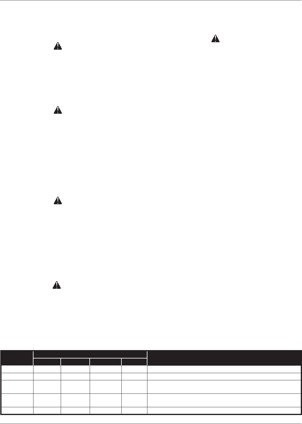
Beaufort Scale
Never operate the machine when wind speeds exceed
12.5 m/s (28 mph) [Beaufort scale 6]. Refer to Figure 1.
BEAUFORT
RATING
WIND SPEED
GROUND CONDITIONS
m/s km/h ft/s mph
3 3,4~5,4 12,25~19,4 11.5~17.75 7.5~12.0 Papers and thin branches move, ags wave.
4 5,4~8,0 19,4~28,8 17.75~26.25 12.0~18 Dust is raised, paper whirls up, and small branches sway.
5 8,0~10,8 28,8~38,9 26.25~35.5 18~24.25
Shrubs with leaves start swaying. Wave crests are apparent in ponds
or swamps.
6 10,8~13,9 38,9~50,0 35.5~45.5 24.5~31
Tree branches move. Power lines whistle. It is difcult to open an
umbrella.
7 13,9~17,2 50,0~61,9 45.5~56.5 31.~38.5 Whole trees sway. It is difcult to walk against the wind.
Figure 1 – Beaufort Scale