
Owner manual


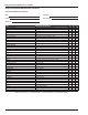


Table Of Contents
- Chapter 1 – Introduction
- Aerial Platform Features
- Options
- Operator’s Manual
- Safety Alerts
- Operation
- Maintenance
- Manual of Responsibilities
- Additional Information
- Component Identification
- Working Envelope
- General Specifications
- Electrocution Hazards
- Minimum Safe Approach Distance
- Prestart Inspection
- Work Place Inspection and Practices
- Operation
- Tip-Over and Falling Hazards
- Electrical System
- Hydraulic System
- Placards and Decals
- Emergency Stop Controls
- Emergency Power System
- Ground Operation Switch
- Platform Foot Switch
- Guardrails
- Lanyard Anchors
- Tilt Alarm
- Ground Fault Circuit Interrupter
- Horn
- Drive Motion Alarm
- Lowering Alarm
- Flashing Light
- Hour Meter
- Battery Level Indicator
- Battery Charge Indicator
- Hydraulic Fluid Filter Gauge
- Fluid Level Sight Gauge
- General Maintenance
- Charging
- Battery Disconnect Switch
- Lower Controls
- Circuit Breaker Reset Buttons
- Upper Controls
- Operator’s Manual Holder
- Electrical System
- Cables and Wiring Harness
- Hydraulic System
- Tires and Wheels
- Lower Control Station
- Level Sensor
- Flashing Light
- Structures
- Upper Control Station
- Drive Motion Alarm
- Lowering Alarm
- Placards and Decals
- Prestart Inspection Checklist
- Cold Weather Start-Up
- Preparing for Operation
- Lower Controls
- Upper Controls
- Gradeability
- Electrical Power Outlet
- Air Line
- Stowing
- Transporting
- Emergency Power System
- Towing
- Troubleshooting Chart
- Table of Contents
- Introduction
- Component Identification
- Special Limitations
- Controls and Indicators
- Battery Disconnect Switch
- Lower Controls
- Circuit Breaker Reset Buttons
- Upper Controls
- Preheat Switch
- Start Switch
- Emergency Stop Button
- Drive Joystick
- Steer Switch
- Drive Range Switch
- Boom Speed Knob
- Rotation Switch
- Riser Switch
- Boom Elevation Switch
- Boom Extension Switch
- Jib Articulation Switch
- Platform Level Switch
- Platform Rotation Switch
- Engine/Emergency Power Switch
- Horn Switch
- Platform Foot Switch
- AC Generator Switch
- Hydraulic Oil Warm-Up Switch
- Pre-Operation Safety Inspection
- System Function Inspection
- Operation
- Cold Weather Start-Up
- Hydraulic System Cold Weather Warm-Up
- Hydraulic System Warm-Up Switch
- Manually Warming The Hydraulic System
- Preparing for Operation
- Lower Controls
- Upper Controls
- Boom Operation
- Driving and Steering
- Drive Speeds
- Pivoting Front Axle
- All Motion Alarm
- Electrical Power Outlet
- AC Generator
- Air Line
- Emergency Lowering
- Lower Controls
- Upper Controls
- After Use Each Day
- Transporting the Machine
- Maintenance
- Inspection and Maintenance Schedule
- Daily Preventative Maintenance Checklist
- Specifications
Specications
A46JRT – 0260228 23
Specications
Aerial Platform
Working height 16.3 m (53′ 6″)
Maximum platform height 14.3 m (46′ 10″)
Up and over height 7.8 m (25′ 8″)
Maximum horizontal reach 7.4 m (24′ 6″)
Main boom
Articulation 0° to +72°
Extension 2.0 m (80″)
Jib
Articulation -70° to +70°
Extension 1.5 m (5′)
Tail swing 0
Turntable rotation 360° non-continuous
Turning radius
Inside 0.8 m (32″)
Outside 3.1 m (10′ 5″)
Wheelbase 2.5 m (8′ 6″)
Ground clearance 33 cm (13″)
Maximum wheel load 4,470 kg (9,850 lb)
Maximum ground pressure 8.8 kg/cm² (125 psi)
Weight, EVW
Approximate 6,622 kg (14,600 lb)
Width 2.1 m (6′ 10″)
Stowed length 5.6 m (18′ 8″)
Stowed height 2.1 m (7′ 2″)
Platform
Dimensions
Standard steel 99 cm x 183 cm (39″ x 72″)
Rated work load 227 kg (500 lb)
Optional Aluminum 76 cm x 244 cm (30″ x 96″)
Rated work load 227 kg (500 lb)
Optional Aluminum 76 cm x 153 cm (30″ x 60″)
Rated work load 250 kg (550 lb)
Toeboard height 15.2 cm (6″)
Rotation 80° CW to 80° CCW
Maximum number of occupants 2 people
Optional AC generator 220 V, 2,000 W
Function Speed
Turntable rotation 65 to 85 seconds
Riser
Up 35 to 40 seconds
Down 20 to 25 seconds
Main boom
Up 25 to 30 seconds
Down 20 to 25 seconds
Extend 20 to 25 seconds
Retract 22 to 27 seconds
Platform rotation 16 to 20 seconds
Jib
Up 20 to 25 seconds
Down 30 to 35 seconds
Drive
High, booms stowed 7.2 km/h (4.5 mph)
Low, booms raised/extended 1.2 km/h (0.8 mph)
Drive System
Standard Four wheel drive
Gradeability – theoretical 45%
Tires
Bar lug 355/55D625NHS, 14 ply
Electrical System
Voltage 12 V DC negative chassis ground
Source One - 12 V 600 CCA battery
Fluid recommended distilled water
Hydraulic System
Drive circuit max. pressure 34,473 kPa (5,000 psi)
Boom circuit max. pressure 18,960 kPa (2,750 psi)
Reservoir capacity 94 l (25 US gal)
System capacity 162 l (43 US gal)
Maximum operating temperature 93°C (200°F)
Hydraulic fluid recommended
Above -12°C (10°F) Mobil DTE-13M (ISO VG32)
Below -12°C (10°F) Mobil DTE-11M (ISO VG15)
Engine
Diesel Kubota V1505-T
Fuel Tank Capacity
Diesel 94 l (25 US gal)
Ambient Air Temperature Operating Range
Celsius -18°C to 43°C
Fahrenheit 0°F to 110°F
Maximum Wind Speed
Gust or steady 45 km/h (28 mph)
12.5 m/s – Beaufort scale 6
Vibration less than 2.5 m/sec
2
0.3 m/sec
2
(measured)
Sound Power Level below 107 dB(A)
Sound Pressure Level
At work station below 100 dB(A)
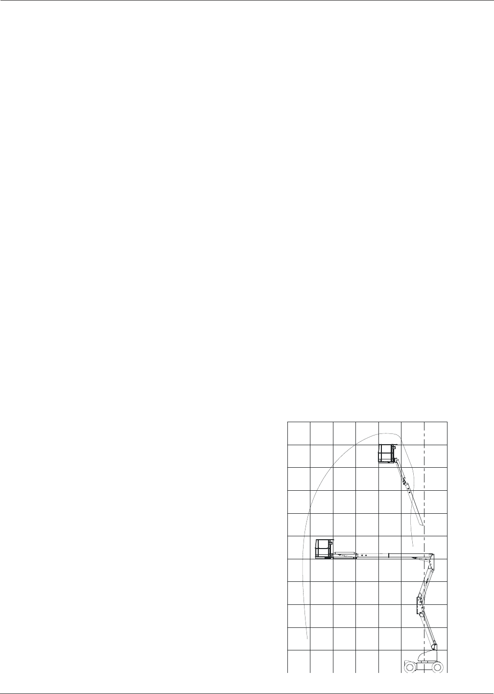
Working Envelope
4.5
(15)
6.1
(20)
9.1
(30)
7.6
(25)
3.0
(10)
1.5
(5)
Meters
(Feet)
3.0
(10)
13.7
(45)
6.1
(20)
9.1
(30)
12.2
(40)
15.2
(50)
16.7
(55)
0
1.5
(5)
4.5
(15)
7.6
(25)
10.6
(35)