
Owner manual


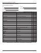


Table Of Contents
- Chapter 1 – Introduction
- Aerial Platform Features
- Options
- Operator’s Manual
- Safety Alerts
- Operation
- Maintenance
- Manual of Responsibilities
- Additional Information
- Component Identification
- Working Envelope
- General Specifications
- Electrocution Hazards
- Minimum Safe Approach Distance
- Prestart Inspection
- Work Place Inspection and Practices
- Operation
- Tip-Over and Falling Hazards
- Electrical System
- Hydraulic System
- Placards and Decals
- Emergency Stop Controls
- Emergency Power System
- Ground Operation Switch
- Platform Foot Switch
- Guardrails
- Lanyard Anchors
- Tilt Alarm
- Ground Fault Circuit Interrupter
- Horn
- Drive Motion Alarm
- Lowering Alarm
- Flashing Light
- Hour Meter
- Battery Level Indicator
- Battery Charge Indicator
- Hydraulic Fluid Filter Gauge
- Fluid Level Sight Gauge
- General Maintenance
- Charging
- Battery Disconnect Switch
- Lower Controls
- Circuit Breaker Reset Buttons
- Upper Controls
- Operator’s Manual Holder
- Electrical System
- Cables and Wiring Harness
- Hydraulic System
- Tires and Wheels
- Lower Control Station
- Level Sensor
- Flashing Light
- Structures
- Upper Control Station
- Drive Motion Alarm
- Lowering Alarm
- Placards and Decals
- Prestart Inspection Checklist
- Cold Weather Start-Up
- Preparing for Operation
- Lower Controls
- Upper Controls
- Gradeability
- Electrical Power Outlet
- Air Line
- Stowing
- Transporting
- Emergency Power System
- Towing
- Troubleshooting Chart
- Table of Contents
- Introduction
- Component Identification
- Special Limitations
- Controls and Indicators
- Battery Disconnect Switch
- Lower Controls
- Circuit Breaker Reset Buttons
- Upper Controls
- Preheat Switch
- Start Switch
- Emergency Stop Button
- Drive Joystick
- Steer Switch
- Drive Range Switch
- Boom Speed Knob
- Rotation Switch
- Riser Switch
- Boom Elevation Switch
- Boom Extension Switch
- Jib Articulation Switch
- Platform Level Switch
- Platform Rotation Switch
- Engine/Emergency Power Switch
- Horn Switch
- Platform Foot Switch
- AC Generator Switch
- Hydraulic Oil Warm-Up Switch
- Pre-Operation Safety Inspection
- System Function Inspection
- Operation
- Cold Weather Start-Up
- Hydraulic System Cold Weather Warm-Up
- Hydraulic System Warm-Up Switch
- Manually Warming The Hydraulic System
- Preparing for Operation
- Lower Controls
- Upper Controls
- Boom Operation
- Driving and Steering
- Drive Speeds
- Pivoting Front Axle
- All Motion Alarm
- Electrical Power Outlet
- AC Generator
- Air Line
- Emergency Lowering
- Lower Controls
- Upper Controls
- After Use Each Day
- Transporting the Machine
- Maintenance
- Inspection and Maintenance Schedule
- Daily Preventative Maintenance Checklist
- Specifications

Daily Preventative Maintenance Checklist
22 A46JRT – 0260228
ITEM INSPECTION OR SERVICES Y N R
Operator’s Manual In place, all pages readable and intact
Engine
Oil level Between full and add marks
Coolant Proper fluid level
Radiator Cap tight, good condition and clean
Fuel tank and line Tank full, cap in place and tight/ no leaks
Electrical System
Battery Condition and charged for proper operation
Battery fluid level and terminals Proper level/clean, connectors tight
Cables and wiring harness No wear or physical damage
Hydraulic System
Fluid level Visible in sight glass
Fluid filter Verify operation in the green zone
Hose, tubes and fittings No leaks
Cold weather warm-up Proper operation
Tires
Air filled Good condition, proper inflation
Foam filled Good condition
Wheels All wheel lug nuts present and properly torqued
Lower Control Station
Operating controls Proper operation
Emergency stop and emergency power Shuts off lower controls/proper operation
Level Sensor Sounds tilt alarm
Flashing Light Proper operation
All Motion Alarm Sounds when machine is operated and/or driven
Structures
Weldments – Chassis, turntable, booms, platform, etc. Welds intact, no damage or deformation
Slide pads In place, no damage or deformation
Fasteners In place and tight.
Upper Control Station
Guardrail system and lanyard anchors Welds intact, no damage or deformation
Operating controls –
Boom functions, drive, brakes, etc.
Proper operation
Emergency stop and emergency power Shuts off upper controls/proper operation
Horn Sounds when activated
Electrical power outlet – GFCI Proper operation
Placards and Decals In place and readable
Maintenance Table Key: Y = Yes/Acceptable, N = No/Not Acceptable, R = Repaired/Acceptable
Daily Preventative Maintenance Checklist
Preventative Maintenance Report
Date:
Owner:
Model No:
Serial No:
Serviced By: