
Owner manual


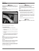

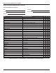


Table Of Contents
- Chapter 1 – Introduction
- Aerial Platform Features
- Options
- Operator’s Manual
- Safety Alerts
- Operation
- Maintenance
- Manual of Responsibilities
- Additional Information
- Component Identification
- Working Envelope
- General Specifications
- Electrocution Hazards
- Minimum Safe Approach Distance
- Prestart Inspection
- Work Place Inspection and Practices
- Operation
- Tip-Over and Falling Hazards
- Electrical System
- Hydraulic System
- Placards and Decals
- Emergency Stop Controls
- Emergency Power System
- Ground Operation Switch
- Platform Foot Switch
- Guardrails
- Lanyard Anchors
- Tilt Alarm
- Ground Fault Circuit Interrupter
- Horn
- Drive Motion Alarm
- Lowering Alarm
- Flashing Light
- Hour Meter
- Battery Level Indicator
- Battery Charge Indicator
- Hydraulic Fluid Filter Gauge
- Fluid Level Sight Gauge
- General Maintenance
- Charging
- Battery Disconnect Switch
- Lower Controls
- Circuit Breaker Reset Buttons
- Upper Controls
- Operator’s Manual Holder
- Electrical System
- Cables and Wiring Harness
- Hydraulic System
- Tires and Wheels
- Lower Control Station
- Level Sensor
- Flashing Light
- Structures
- Upper Control Station
- Drive Motion Alarm
- Lowering Alarm
- Placards and Decals
- Prestart Inspection Checklist
- Cold Weather Start-Up
- Preparing for Operation
- Lower Controls
- Upper Controls
- Gradeability
- Electrical Power Outlet
- Air Line
- Stowing
- Transporting
- Emergency Power System
- Towing
- Troubleshooting Chart
- Table of Contents
- Introduction
- Component Identification
- Special Limitations
- Controls and Indicators
- Battery Disconnect Switch
- Lower Controls
- Circuit Breaker Reset Buttons
- Upper Controls
- Preheat Switch
- Start Switch
- Emergency Stop Button
- Drive Joystick
- Steer Switch
- Drive Range Switch
- Boom Speed Knob
- Rotation Switch
- Riser Switch
- Boom Elevation Switch
- Boom Extension Switch
- Jib Articulation Switch
- Platform Level Switch
- Platform Rotation Switch
- Engine/Emergency Power Switch
- Horn Switch
- Platform Foot Switch
- AC Generator Switch
- Hydraulic Oil Warm-Up Switch
- Pre-Operation Safety Inspection
- System Function Inspection
- Operation
- Cold Weather Start-Up
- Hydraulic System Cold Weather Warm-Up
- Hydraulic System Warm-Up Switch
- Manually Warming The Hydraulic System
- Preparing for Operation
- Lower Controls
- Upper Controls
- Boom Operation
- Driving and Steering
- Drive Speeds
- Pivoting Front Axle
- All Motion Alarm
- Electrical Power Outlet
- AC Generator
- Air Line
- Emergency Lowering
- Lower Controls
- Upper Controls
- After Use Each Day
- Transporting the Machine
- Maintenance
- Inspection and Maintenance Schedule
- Daily Preventative Maintenance Checklist
- Specifications
Maintenance
20 A46JRT – 0260228
Maintenance
Warning
Always block the elevating assembly whenever it is
necessary to perform maintenance while the platform
is elevated.
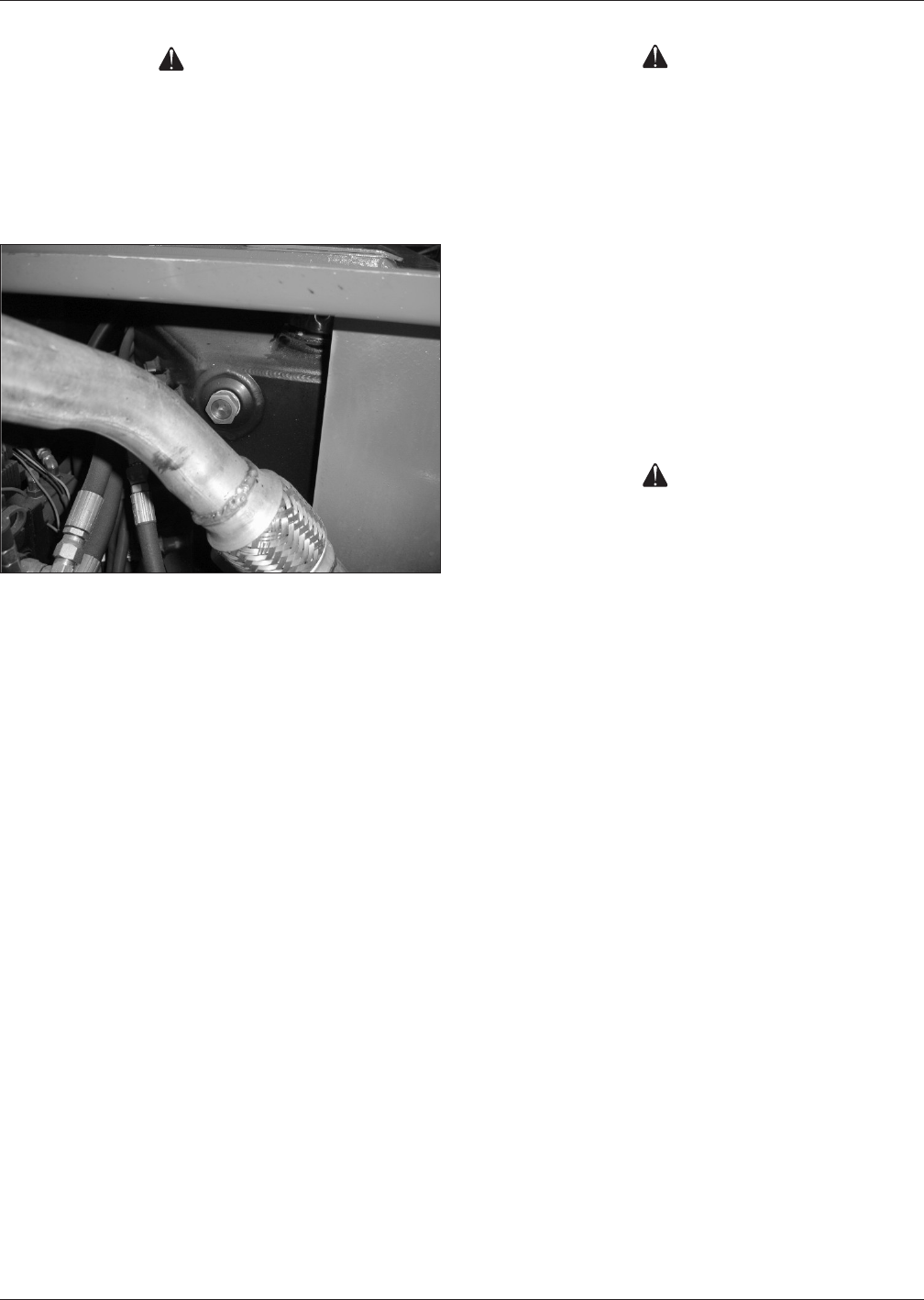
Hydraulic Fluid
The hydraulic fluid reservoir is located in the engine
compartment. Refer to Figure 7.
Figure 7 – Hydraulic Fluid Reservoir
Note
Never add fluid if the platform is elevated.
Check Hydraulic Fluid
1. Make sure that the platform is fully lowered.
2. Remove the engine cover to access the engine
compartment.
3. Visually check to make sure the fluid is visible in the
sight glass.
4. If necessary, remove the filler cap and add fluid of
the proper type. Replace the cap making sure it is
tightly in place. See “Specifications” on page 18.
Engine
Remove the keeper pins and release the latches on either
side of the engine cover and visually inspect the engine
and its components with the engine off.
Oil Level
Check the engine oil level before starting the engine
so the oil has drained to the pan. The proper oil level is
between the add and full marks on the dipstick.
The distance between the top and bottom dipstick marks
corresponds to about 1 l (1 quart US). Add oil, if neces-
sary, before starting the engine.
Battery Maintenance
Warning
Hazard of explosive gas mixture. Keep sparks, flame,
and smoking material away from batteries.
Always wear safety glasses when working near bat-
teries.
Battery fluid is highly corrosive. Thoroughly rinse
away any spilled fluid with clean water.
Check the battery uid level daily, especially if the
machine is being used in a warm, dry climate.
If electrolyte level is lower than 6 mm (¼″) above
the plates add distilled water only. DO NOT use tap
water with high mineral content, as it will shorten
battery life.
Keep the terminals and tops of the batteries clean.
Warning
Always use manufacturer approved replacement
parts.
•
•
•