
Owner manual


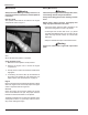

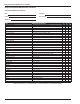


Table Of Contents
- Chapter 1 – Introduction
- Aerial Platform Features
- Options
- Operator’s Manual
- Safety Alerts
- Operation
- Maintenance
- Manual of Responsibilities
- Additional Information
- Component Identification
- Working Envelope
- General Specifications
- Electrocution Hazards
- Minimum Safe Approach Distance
- Prestart Inspection
- Work Place Inspection and Practices
- Operation
- Tip-Over and Falling Hazards
- Electrical System
- Hydraulic System
- Placards and Decals
- Emergency Stop Controls
- Emergency Power System
- Ground Operation Switch
- Platform Foot Switch
- Guardrails
- Lanyard Anchors
- Tilt Alarm
- Ground Fault Circuit Interrupter
- Horn
- Drive Motion Alarm
- Lowering Alarm
- Flashing Light
- Hour Meter
- Battery Level Indicator
- Battery Charge Indicator
- Hydraulic Fluid Filter Gauge
- Fluid Level Sight Gauge
- General Maintenance
- Charging
- Battery Disconnect Switch
- Lower Controls
- Circuit Breaker Reset Buttons
- Upper Controls
- Operator’s Manual Holder
- Electrical System
- Cables and Wiring Harness
- Hydraulic System
- Tires and Wheels
- Lower Control Station
- Level Sensor
- Flashing Light
- Structures
- Upper Control Station
- Drive Motion Alarm
- Lowering Alarm
- Placards and Decals
- Prestart Inspection Checklist
- Cold Weather Start-Up
- Preparing for Operation
- Lower Controls
- Upper Controls
- Gradeability
- Electrical Power Outlet
- Air Line
- Stowing
- Transporting
- Emergency Power System
- Towing
- Troubleshooting Chart
- Table of Contents
- Introduction
- Component Identification
- Special Limitations
- Controls and Indicators
- Battery Disconnect Switch
- Lower Controls
- Circuit Breaker Reset Buttons
- Upper Controls
- Preheat Switch
- Start Switch
- Emergency Stop Button
- Drive Joystick
- Steer Switch
- Drive Range Switch
- Boom Speed Knob
- Rotation Switch
- Riser Switch
- Boom Elevation Switch
- Boom Extension Switch
- Jib Articulation Switch
- Platform Level Switch
- Platform Rotation Switch
- Engine/Emergency Power Switch
- Horn Switch
- Platform Foot Switch
- AC Generator Switch
- Hydraulic Oil Warm-Up Switch
- Pre-Operation Safety Inspection
- System Function Inspection
- Operation
- Cold Weather Start-Up
- Hydraulic System Cold Weather Warm-Up
- Hydraulic System Warm-Up Switch
- Manually Warming The Hydraulic System
- Preparing for Operation
- Lower Controls
- Upper Controls
- Boom Operation
- Driving and Steering
- Drive Speeds
- Pivoting Front Axle
- All Motion Alarm
- Electrical Power Outlet
- AC Generator
- Air Line
- Emergency Lowering
- Lower Controls
- Upper Controls
- After Use Each Day
- Transporting the Machine
- Maintenance
- Inspection and Maintenance Schedule
- Daily Preventative Maintenance Checklist
- Specifications
Transporting the Machine
A46JRT – 0260228 19
Transporting the Machine
Preparing for Transportation
Use the following procedure to prepare the aerial platform
for transportation.
1. Remove any unnecessary tools, materials, or other
loose objects from the platform.
2. Close and latch the battery trays and cowling
doors.
By Crane
Danger
Lifting by Crane is for transport purposes only. Stand
clear of the machine when lifting.
See Specifications for weight of machine and be
certain that the crane is of adequate capacity to lift
the machine.
1. Insure that the boom is fully lowered.
2. Attach straps to the chassis lifting lugs only. Insure
that the straps are adjusted properly to keep the unit
level when lifting.
By Transport Vehicle
Use the following procedure to secure the aerial platform
on the transport vehicle.
1. Chock the wheels.
2. Remove all personnel, tools, materials, or other loose
objects from the platform.
3. Raise the main boom about 0.3 m (1′).
4. Place a large wood block under the platform support
braces (refer to Figure 5). Lower the platform so it
rests on the wood block.
5. Place the lower controls emergency stop switch in
the off position. Turn the start switch off and remove
the key.
Figure 5 – Platform
6. Turn the battery disconnect switch off and close and
latch the battery trays and cowling doors.
7. Use wire-ties to fasten the gravity gates to the
guardrails to prevent the them from bouncing. Also,
use wire-ties to fasten the platform foot switch to the
platform floor.
Caution
Ratchets, winches, and come-alongs may produce
enough force to damage machine components. Do
not over tighten the straps or chains when securing
the aerial platform to the transport vehicle.
8. Use a nylon strap to securely fasten the platform
against the wood block. Thread the strap through
the tie-down lugs at the front of the platform.
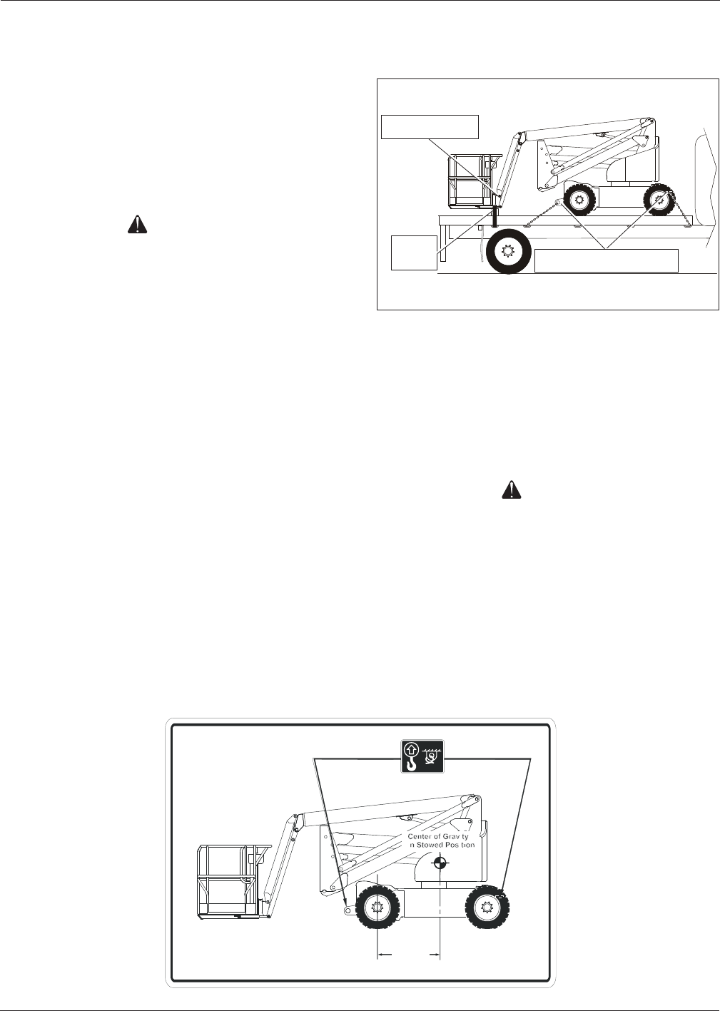
9. Use chains or straps to securely fasten the aerial
platform to the transport vehicle using the tie-down
lugs as attachment points. Proper tie-down and haul-
ing are the responsibility of the carrier.
Wood
Block
Tie-Down/Lifting Lugs
Wood
Block
Tie-Down/Lifting Lugs
Tie-Down Lugs
026 04 42
Tie-D o w n /Liftin g L u g
(45")
ap prox im ate
1.15 m
008 34 27
Figure 6 – Center of Gravity