Operator’s Manual Part Number 0260228 June 2010 March 2010
Table of Contents Table of Contents Declaration of Conformity............................................2 Safety Rules................................................................3 Introduction..................................................................4 Component Identification.............................................4 Special Limitations......................................................5 Platform Capacity.....................................................5 Manual Force...............
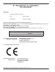
EC DECLARATION OF CONFORMITY FOR MACHINERY MACHINERY: Powered Aerial Platform known as: Type: Snorkel A46JRT Serial Number: A46JRT-04-XXXXXX The machine specified above conforms to the following provisions: Machinery directive 2006/42/EC (using document EC Community Legislation on Machinery and taking guidance from EN280:2001 + Amendment A2:2009) Council Directive 2004/108/EC on Electromagnetic Compatibility Council Directive 2006/95/EC on Low Voltage Equipment Safety Council Dire
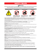
SAFETY RULES Warning All personnel shall carefully read, understand and follow all safety rules and operating instructions before operating or performing maintenance on any Snorkel aerial work platform.
Introduction Introduction This manual covers the A46JRT Aerial Work Platform. This manual must be stored on the machine at all times. When contacting Snorkel for service or parts information, be sure to include the MODEL and SERIAL NUMBERS from the equipment nameplate. Should the nameplate be missing, the SERIAL NUMBER is also stamped on top of the chassis at the front of the machine. Read, understand and follow all safety rules and operating instructions before attempting to operate the machine.
Special Limitations Special Limitations Travel with the platform raised is limited to creep speed range. Elevating the platform is limited to firm, level surfaces only. If the platform overload sensing system is tripped while operating the machine, the emergency power system may still be used for emergency machine operation. Danger Danger The elevating function shall ONLY be used when the work platform is level and on a firm surface. Platform Capacity Two people and tools may occupy the platform.
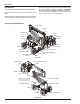
Controls and Indicators Controls and Indicators The operator shall know the location of each control and indicator and have a thorough knowledge of the function and operation of each before attempting to operate the machine. 18. Main control circuit breaker 19. Platform overload light 34 37 22 35 33 25 29 32 26 1 27 28 30 23 31 24 Figure 2 – Battery Disconnect Switch 36 1.
Controls and Indicators Battery Disconnect Switch The battery disconnect is located at the left rear of the chassis (refer to Figure 2). The battery disconnect removes electrical power from all electrically controlled functions when in the off position. • Place the switch in the on position to electrically connect the battery to the electrical system. Caution Only authorized personnel should operate the aerial platform. Unqualified personnel may cause injury to coworkers or property damage.
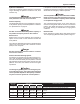
Controls and Indicators • Hold the switch downward to lower the jib. Platform Level Switch The platform level switch (refer to Figure 3) is used to level the platform floor with respect to the ground. The switch is spring returned to the center off position. • Hold the switch upward to tilt the platform floor upward or away from the ground. • Hold the switch downward to tilt the platform floor downward or toward the ground.
Controls and Indicators Upper Controls The upper controls (refer to Figure 4) are located on the control panel at the platform. Boom, platform, and drive functions can be operated from the upper controls. The following controls are located on the upper control panel. Preheat Switch The preheat switch (refer to Figure 4) is a momentarily on toggle switch. This switch operates the glow plugs to aid in starting the engine when the start switch is in the on position.
Controls and Indicators Rotation Switch The rotation switch (refer to Figure 4) is used to rotate the turntable in a clockwise or counterclockwise direction. The switch is spring returned to the center off position. • Hold the switch to the right to rotate the turntable counterclockwise. • Hold the switch to the left to rotate the turntable clockwise. Riser Switch The riser switch (refer to Figure 4) is used to raise or lower the riser booms. The switch is spring returned to the center off position.
Controls and Indicators Caution Not all hydraulic fluid is suitable to use in the hydraulic system. Some have poor lubricating characteristics and may increase component wear. Only use hydraulic fluid as recommended. 2. Place the hydraulic fluid warm-up switch in the on position. • The engine throttle speed will increase to warm the hydraulic fluid. Use cold weather hydraulic oil as recommended in the machine General Specifications in temperatures of -12°C (10°F) or below.
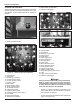
Pre-Operation Safety Inspection Pre-Operation Safety Inspection Note Carefully read, understand and follow all safety rules, operating instructions, labels and National Safety Instructions/Requirements. Perform the following steps each day before use. 1. Open the turntable covers and inspect for damage, fluid leaks or missing parts. 2. Check the level of the hydraulic fluid with the platform fully lowered. The fluid level must visible in the sight glass. Add recommended hydraulic fluid if necessary.
System Function Inspection System Function Inspection Refer to “Controls and Indicators” on page 6 for the locations of various controls and indicators. Warning STAND CLEAR of the work platform while performing the following checks. Before operating the machine, survey the work area for surface hazards such as holes, drop-offs, bumps and debris. Check in ALL directions, including above the work platform, for obstructions and electrical conductors. 1.
Operation Operation The aerial platform may be operated from either the lower or upper controls. Danger The aerial platform is not electrically insulated. Death or serious injury will result from contact with, or inadequate clearance from, an energized conductor. Do not go closer than the minimum safe approach distance as defined by national safety regulations. Pinch points may exist between moving components.
Operation Preparing for Operation Use the following procedure to prepare the aerial platform for operation. 7. Place the ground operation switch in the off position when no functions are being operated. 1. Perform a prestart inspection as described in the “Daily Preventative Maintenance Checklist” on page 22. Upper Controls The upper controls may be used for driving the aerial platform and positioning the booms and platform while on the job. 2. Place the battery disconnect switch in the on position.
Operation Driving and Steering Use the following procedure to operate the drive and steer functions. Danger The aerial platform can tip over if it becomes unstable. Death or serious injury will result from a tip-over accident. Do not drive an elevated aerial platform on soft, uneven, or sloping surfaces. Do not drive the machine on grades that exceed 40 percent.
Operation • To avoid a sudden speed change from high to low elevated boom speed, always bring the machine to a stop before raising the booms from the stowed position. Warning The potential for an accident increases when safety devices do not function properly. Death or serious injury could result from such accidents. Do not alter, disable, or override any safety device. Do not use the aerial platform if it drives faster than 1.28 km/h (0.8 miles per hour) [10.
Operation Only use the emergency power system if the main power system fails. Lower Controls Use the following procedure to operate the machine using the emergency power system from the lower controls. 1. Place the battery disconnect switch in the on position. 2. Place the key in the control selector switch and turn it to the ground position. 3. Pull the emergency stop button outward. 4.
Transporting the Machine Transporting the Machine Preparing for Transportation Use the following procedure to prepare the aerial platform for transportation. 1. Remove any unnecessary tools, materials, or other loose objects from the platform. 5. Place the lower controls emergency stop switch in the off position. Turn the start switch off and remove the key. Tie-Down Lugs 2. Close and latch the battery trays and cowling doors. By Crane Danger Lifting by Crane is for transport purposes only.
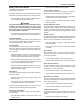
Maintenance Maintenance Battery Maintenance Warning Always block the elevating assembly whenever it is necessary to perform maintenance while the platform is elevated. Hydraulic Fluid The hydraulic fluid reservoir is located in the engine compartment. Refer to Figure 7. Warning Hazard of explosive gas mixture. Keep sparks, flame, and smoking material away from batteries. Always wear safety glasses when working near batteries. Battery fluid is highly corrosive.
Inspection and Maintenance Schedule Inspection and Maintenance Schedule Caution Frequency and extent of periodic examinations may depend on national regulations. The Complete Inspection consists of periodic visual and operational checks, along with periodic minor adjustments that assure proper performance. Daily inspection will prevent abnormal wear and prolong the life of all systems.
Daily Preventative Maintenance Checklist Daily Preventative Maintenance Checklist Preventative Maintenance Report Date: Serial No: Owner: Serviced By: Model No: ITEM INSPECTION OR SERVICES Operator’s Manual In place, all pages readable and intact Y N R Engine Oil level Between full and add marks Coolant Proper fluid level Radiator Cap tight, good condition and clean Fuel tank and line Tank full, cap in place and tight/ no leaks Electrical System Battery Condition and charged for proper
Specifications Specifications Aerial Platform Working height Maximum platform height Up and over height Maximum horizontal reach Main boom Articulation Extension Jib Articulation Extension Tail swing Turntable rotation Turning radius Inside Outside Wheelbase Ground clearance Maximum wheel load Maximum ground pressure Weight, EVW Approximate Width Stowed length Stowed height 16.3 m (53′ 6″) 14.3 m (46′ 10″) 7.8 m (25′ 8″) 7.4 m (24′ 6″) 0° to +72° 2.0 m (80″) -70° to +70° 1.
Local Distributor: Lokaler Vertiebshändler: Distributeur local: El Distribuidor local: ll Distributore locale: USA Europe Phone: 1 (785) 989 3000 Toll Free: 1 (800) 255 0317 Fax: 1 (785) 989 3070 Phone: +44 (0) 845 1550 057 Fax: +44 (0) 845 1557 756