
Manual

Troubleshooting
Section
5-6 A38E Work Platform
5.7
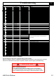
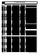
GP400 I/O allocations
Sch. 15 500 430
AB 38 Rev 1
U# PCB 59 100 026
same hardware as 21 510 436
P4-12 J6-12 23 Safe High side output 48V protected See Note 1 Line contactor
P4-13 J6-13 23 Safe High side output Brake unlock
P4-14 J6-14 23 Safe High side output Brake unlock
P4-15 J6-15 23 Safe High side output 48V protected
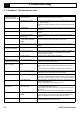
P5-1 J5-1 17 High side PWM output
P5-2 J5-2 16 High side 2A output
P5-3 J5-3 16 High side 2A output
P
5-4 J5-4 17 High side PWM output
P5-5 J5-5 17 High side 2A output
P5-6 J5-6 16 High side 2A output
P5-7 J5-7 18 High side PWM output
P5-8 J5-8 18 High side PWM output
P5-9 J5-9 16 High side 2A output
P5-10 J5-10 18 High side PWM output
P5-11 J5-11 18 High side PWM output
P5-12 J5-12 15 High side 2A output
P5-13 J5-13 B+ protected Supply (PTC 140mA)
P5-14 J5-14 19 High side 2A output
P5-15 J5-15 17 High side PWM output
P6-1 J4-1 14 High side 2A ou
tput Lower Boom up
V8
P6-2 J4-2 13 High side 2A output Lower Boom down
P6-3 J4-3 13 High side 2A output Upper boom up
V7
P6-4 J4-4 14 High side 2A output Upper boom down
P6-5 J4-5 13 High side 2A output Tele out
V6
P6-6 J4-6 13 High side 2A output Tele in
P6-7 J4-7 14 High side 2A output Steer left
V5
P6-8 J4-8 12 High side 2A output Steer right
P6-9 J4-9 12 High side 2A output Turntable CW
V4
P6-10 J4-10 14 High side 2A output Turntable CCW
P6-11 J4-11 12 High side 2A output Basket level up
P6-12 J4-12 12 High side 2A output Basket level down
P6-13 J4-13 15 High side 2A output
P6-14 J4-14 15 High side 2A output
P6-15 J4-15 15 High side 2A output Buzzer
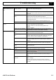
P7-1 J3-1 B+ Digital Input Valve supply
from P600
P7-2 J3-2 B+ Digital Input Valve & Logic supply (ground mode) Key sw grnd mode
also to P600
P7-3 J3-3 B+ Digital Input Elevation sw.
P7-4 J3-4 B+ Digital Input Logic supply (platform mode) Key sw platform mode
also to P600
P7-5 J3-5 B+ Digital Input Lower boom sw.
P7-6 J3-6 B+ Digital Input Upper boom sw.
P7-7 J3-7 B+ Digital Input Tele sw.
P7-8 J3-8 B+ Digital Input Turntable sw.
P7-9 J3-9 B+ Digital Input
P7-10 J3-10 B+ Digital Input
P7-11 J3-11 B+ Digital Input
P7-12 J3-12 B+ Digital Input
P7-13 J3-13 B- Digital Input
P7-14 J3-14 B- Digital Input
P7-15 J3-15 B- Digital Input
P8-1 J2-1 Analog Input gnd finger joystick Ground control; direction and propor
tional control of
gnd control selected function Std 0.5V/2.5V/4.5V
P8-2 J2-2 Safe Analog Input
P8-3 J2-3 Analog Input
P8-4 J2-4 Analog Input
P8-5 J2-5 Analog Input
P8-6 J2-6 Safe Analog Input
P8-7 J2-7 Analog Input
P8-8 J2-8 Analog Input
P8-9 J2-9 Analog Input
P8-10 J2-10 No connect
P8-11 J2-11 +5V protected Supply
P8-12 J2-12 +5V protected Supply
P8-13 J2-13 GND gnd finger joystick
P8-14 J2-14 GND
P8-15 J2-15 GND
P15-1 J10-1 B+ Digital Input
P15-2 J10-2 B+ Digital Input
P15-3 J10-3 B+ Digital Input
P15-4 J10-4 B+ Digital Input
P15-5 J10-5 B+ Digital Input
P15-6 J10-6 B+ Digital Input
P15-7 J10-7 B+ Digital Input
P15-8 J10-8 B+ Digital Input
P15-9 J10-9 B+ Digital Input
P15-10 J10-10 B+ protected Supply 140mA PTC shared with 11, 12
P15-11 J10-11 B+ protected Supply 140mA PTC shared with 10, 12
P15-12 J10-12 B+ protected Supply 140mA PTC shared with 10, 11
V9; basket leve
ling only operates when the booms
are fully stowed, elevation sw. closed (B+)
Ground control; enable function, direction and
proportional control from gnd fingerjoystick (P8-1),
need to hold while function
V1 & V2; both powered when driving