
Manual

Troubleshooting
Section
5-5A38E Work Platform
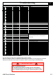
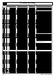
5.1
Platform assembly will not
slew
1. Faulty controller Check the I/O's Using EZcal diagnostics
2. Faulty slew solenoid Check voltage at the solenoid electrical connections.
Use a screw driver or similar component to check the magnetic effect
of solenoid.
3. Incorrect cross-line relief
setting
Insert a pressure gauge in the TP port of the valve block.
Operate a slew function and measure the pressure.
Provided the main relief pressure has been preset properly, the gauge
should register 20-50 bar.
Reset or replace CLRV valves thus preventing bypassing of oil.
4. Faulty slew select switch Replace the complete switch assembly.
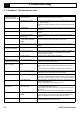
Platform assembly wi
ll not
descend
1. Faulty controller
Check the programmed mast speed settings.
Check the continuity of mast speed enabling cables to the
controller.
Repair as necessary.
2. Faulty mast or jib solenoids Check the voltage to the solenoids V7 & V8 for the mast functions.
Swap solenoids to confirm fault and replace if necessary.
P
ROBLEM
C
AUSE
A
CTION
Check the I/O’s using EZcal diagnostics.
Machine will not steer 1. Malfunction of joystick toggle Check I/O’s using EZcal diagnostics.
switch Remove and service the switch &/or joystick.
2. Faulty steering solenoid &
valve
Check that the solenoids at V5 are energised while the steering
Check the cables feeding these solenoids. Replace the solenoids if
necessary. Check the valve cartridges for contamination.
3. Faulty controller eht fo ytiunitnoc eht kcehC ..scitsongaid lacZE gnisu s’O/I kcehC
steer speed enabling cable to the contr
oller. Repair or repla
ce as
necessary.
4. Steer cylinder malfunction Check the hose connections to the cylinder.
Check the cylinder rod-end pins and the cylinder mounting bolts.
5. Seized wheel mounting frame
pivot(s)
Refer to the maintenance section for assembly and repair of the pivot
and associated parts.
6. Damaged steering link plates Replace the steering link plates, associated pins and lock plates.
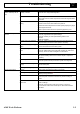
Machine will not drive 1. Temp Reset system and allow the system to cool down.
2.
Towing valve open Locate the towing valve CT 21 on the valve block. Ensure that it is fully
closed by turning clockwise.
3. Incorrect hose connections Refer to the hydraulic diagram for correct connections of valve ports
to the motor ports. Incorrect connection may result
in locking of
wheels.
4. Fail-safe brake-circuit
malfunction
Blocked brake line to either motor. Clear blockage and/or replace
hoses and fittings.
Check the correct function of the check valves V1 and V2 on
the valve block. These valve should open to allow brake chamber
evacuation.