PARTS & SERVICE Part number 514252-200 March 2014 006001 +
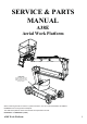
SERVICE & PARTS MANUAL A38E Aerial Work Platform Nameplate The Serial Number of the Work Platform is also stamped on the inside of the Chassis, close to the Steering Cylinder. When contacting Snorkel for service or parts information, sure to include the MODEL and SERIAL NUMBERS from the equipment nameplate. The A38E work platform meets and exceeds the requirements of both: En280:2001 and ANSI A92.
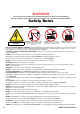
WARNING All personnel shall carefully read, understand and follow all safety rules and operating instructions before operating or performing maintenance on any Snorkel aerial work platform. Safety Rules Electrocution Hazard Tip Over Hazard Collision Hazard Fall Hazard 83 B hg A t i Rp U THIS MACHINE IS NOT INSULATED! NEVER elevate the platform or drive the machine while elevated unless the machine is on a firm, level surface.
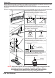
Safety Rules Harness attachment points are provided in the platform and the manufacturer recommends the usage of a fall restraint harness, especially where required by national safety regulations. All harness attachment points on SNORKEL vehicles have been tested with a force of 3,650 lbs (16.3 KN) per person. See below examples of harness attachment points used on SNORKEL vehicles with their corrosponding rating; Harness attachment point Type 1.
NOTES: iv A38E Work Platform
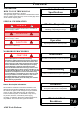
Foreword Introduction HOW TO USE THIS MANUAL This manual is divided into 7 Sections, The right hand pages of each Section is marked with a black section number printed at the top corner of each page which can be used as a quick guide. Introduction & Specifications General Description & Machine Specifications. 1.0 SPECIAL INFORMATION DANGER Indicates an imminently hazardous situation which, if not avoided, will result in severe injury or death.
Foreword NOTES: vi A38E Work Platform
Section Contents i Table of Contents Section No. 1.0 Introduction & Specifications 1.0 1.1 1.2 1.3 2.0 Introduction ........................................................ 1-1 Purpose ..........................................................1-1 Scope ..............................................................1-1 General Information .......................................... 1-1 Platform ..........................................................1-1 Control Box ..................................
Contents Section i Table of Contents Section No. Page No. 4.15 4.16 4.17 4.18 4.19 4.20 4.21 4.22 5.0 Troubleshooting 5.0 5.1 5.2 6.0 7.0 Page No. Illustrated Parts Breakdown 7.0 7.1 7.2 Introduction ........................................................ 7-1 Index ..................................................................... 7-1 Illustrated Parts Breakdown .......................... 7-2 F inal Assembly A38E .... ............. ................................ Chassis Ass embly .
Contents Section i NOTES: A38E Work Platform III
Section i Contents NOTES: IV A38E Work Platform
Introduction & Specifications 1.0 Introduction PURPOSE The purpose of this Service & Parts Manual is to provide instructions and illustrations for the operation and maintenance of the A38E Work Platform manufactured by Snorkel. (See Figure 1-1). SCOPE The manual includes the procedures and responsibilities which must be strictly adhered to for proper operation, maintenance, adjustment, and repair of this product. The Maintenance Section further covers preventative maintenance and trouble shooting. 1.
Section 1.1 Introduction & Specifications DRIVE & STEER SYSTEMS The A38E Work Platform is restricted to low speed drive when the Platform is raised above the Boom Rest Limit Switch. The Traction controller controls the application of drive from the Joystick by means of two Traction Motors, which are assembled to the drive wheels via a Drive Reduction Gearbox. Steering of the A38E Work Platform is controlled by a double acting cylinder.
Introduction & Specifications 1.2 Specifications ITEM Duty Cycle Platform Size METRIC 45% of 8 hour shift 0.58 m x 1.3 m (inside gaurdrails) IMPERIAL (ANSI) 45% of 8 hour shift 1.77 ft x 4.3 ft (inside gaurdrails) 215 kg Indoors 2 People 2 People 475 lbs Outdoors 1 People 2 People Maximum Working Height Maximum Platform Height Min. Platform Floor Height 13.45 m 11.45 m 0.65 m 44.12 ft 37.56 ft 2.13ft Max. Working Outreach 6.10 m 20.00 ft Platform Height At Maximum Outreach 5.40 m 17.
Section 1.
Machine Preparation Section 2.1 Front Lifting / Tie-down Lug 2.1 Preparation for use CAUTION Read, understand and follow all operating instructions before attempting to operate the machine. Lubricate machine per lubrication instructions in Section 4.4, Maintenance. 2. Fully lower the platform and make sure the machine is stowed securely. 3. Check that the hydraulic oil level is adequate and that it is not over filled.
Machine Preparation Section 2.6 When the A38E is on the Truck it should then be made secure. 1. 2. 4. Chock the wheels of the A38E. Secure the work platform to the transport vehicle with chains or straps of adequate load capacity attached to the lifting lugs on the chassis. When towing is completed, turn both Allen head socket screws in a counter clockwise direction until they rest firmly against the locking circlip.
Machine Preparation Section 2.
Section 2.
Operation 3.0 Introduction GENERAL FUNCTIONING WARNING Before beginning to operate the machine it is a mandatory requirement to read, fully understand and follow the Operators Manual. The A38E Lift and Steer functions are operated by utilising a battery powered electric motor which drives a hydraulic pump. The pump supplies oil under pressure to the various platform functions.
Section 3.0 Operation It will be noticed that on the Upper Control Box a set of switches are used to alternate functions. Each function will have it’s corresponding graphicand lamp. This selector switch indicates to the Controller which function is required and by using the Joystick the speed of this selected function can be adjusted.
Operation 3.1 Safety Rules and Precautions WARNING Before using the A38E Work Platform it is imperative to read, understand and follow the following Safety Rules and Precautions. Section 3.1 DO NOT use in winds exceeding 12.5 m/s (28 mph Beaufort Force 6) NEVER change or modify operating or safety systems. INSPECT the machine thoroughly for cracked welds, loose hardware, hydraulic leaks, damaged control cable, loose wire connections and wheel bolts.
Operation Section 3.2 3.2 Controls and Indicators The controls and indicators for operation of the A38E Work Platform are shown in Figures 3-1 & 3-2. The name and function of each control and indicator are listed in Tables 3-1. The index numbers in the figure correspond to the index numbers in the table. The operator should know the location of each control and indicator and have a thorough knowledge of the function and operation of each before attempting to operate the unit.
Operation 1 (CE) 6 11 8 Section 3.
Operation Section 3.3 3.3 Pre-Operation Inspection WARNING 15. 16. Carefully read, understand and follow all safety rules and operating instructions. Perform the following steps each day before use. DO NOT perform service on Work Platform with the platform elevated unless the elevating assembly is properly supported. 1. 2. 3. 4. 5. 6. 7. 8. Remove module covers and inspect for damage, oil leaks or missing parts.
Operation 3.4 Operation NOTE: Before operating the A38E Work Platform it is imperative that the Pre-Operation Inspection (Section 3.3) has been completed and any deficiencies have been corrected. The operator must also understand the functions of all the controls before operating the machine. ELEVATING & LOWERING THE A38E WORK PLATFORM Before beginning any operation involving the Elevating Assembly the following checks should be carried out.
Operation Section 3.4 5. To “STEER” the A38E activate the Interlock Switch while pushing the Steering Switch LEFT or RIGHT to turn the wheels. Observe the tyres while manoeuvring to ensure proper direction. NOTE: Steering is not self-centring. The wheels must be returned to the straight ahead position by operating the Steering Switch. TRAVEL WITH WORK PLATFORM ELEVATED WARNING Travel with platform elevated ONLY on firm and level surfaces.
Operation ensure a slow controlled rate of descent at all times. Descent can be halted at any time by removing pressure from the red knob. Repeat the operation if necessary for the upper boom when cylinder is in reach of the ground. With both main booms lowered fully it should then be possible to leave the platform safely. 1. 3. Figure 3-2: Emergency Lowering CONTROL FROM GROUND LEVEL 1. 2. Chassis Controls are fitted at the base of the Elevating Assembly.
Section 3.
Operation Section 3.
Section 3.
Maintenance 4.0 Introduction ! WAR RN N II N NG G ! Be sure to read, understand and follow all information in the Operation Section of this manual before attempting to operate or perform service on any A38E Work Platform. This section contains instructions for the maintenance of the A38E Series Work Platform. Procedures for scheduled maintenance and repair/ removal are included. Referring to Section 3.0 and Section 6.
Maintenance Section 4.1 Preventative Maintenance Table Key Interval Daily = each shift or every day 10h/7d = every 10 hours or 7 days 50h/30d = every 50 hours or 30 days 250h/6m = every 250 hours or 6 months 500h/1y = every 500 hours or 1 year 1000h/2y = every 1000 hours or 2 years Y=Yes/Acceptable N=No/Not Acceptable R=Repaired/Acceptable Preventative Maintenance Report Date : _______________________________ Owner : ______________________________ Model No : ____________________________ V.I.
Maintenance 4.2 Battery Maintenance Electrical energy for the motor is supplied by eight 6 volt batteries wired in series to give a 48 volts DC supply. Each of these batteries consist of three cells which can supply a maximum voltage of 2.1V ea =>6.3V per battery =>50.4V per battery pack. Proper care and maintenance of the batteries and motor will ensure maximum performance from the work platform. WARNING Hazard of explosive gas mixture.
Section 4.3 Maintenance All Snorkel battery operated Work Platforms, including the A38E can operate at ambient temperatures to a value of -20ºC (-4ºF). However for this there are two provisions which must be met. The ISO#46 grade of hydraulic oil normally used in Snorkel Work Platforms must be replaced with a grade suitable for these low temperature conditions.
Maintenance 4.4 Lubrication Section 4.4 PIVOT PINS Refer to Table 4-1 and Figure 4-1 for location and lubrication intervals required for the items that necessitate lubrication service. Refer to the appropriate sections for lubrication information on the Hydraulic Oil Tank and Filter. Apply grease liberally to the Pivot Pin and Pin Lock Plate locations using a brush or cloth. Force as much grease as possible between the Pins & Pin Lock Plates and the Weldments. Wipe away all excess grease.
Maintenance Section 4.5 2. Provide a suitable container to catch the drained oil. Hydraulic tank has a capacity of 25 Litres (6.5 Gallons US). Remove the drain plug on the lower side and allow all oil to drain. Clean the magnetic drain plug and reinstall. Disconnect the return hose and hose fitting from inlet port of the hydraulic return filter. Loosen and remove the filter cover retaining bolts. Remove filter (10 micron) assembly. Replace with a new filter.
Maintenance SLEW CROSS-LINE RELIEF VALVES 1. 2. 3. 4. 5. 6. 7. Repeat steps 1-3 as outlined above Loosen Locknuts on both cross-line relief valves and turn adjusting screws anticlockwise two full turns. Operate slew function from lower controls and rotate the Elevating Assembly until the slew stop prevents further rotation. Slowly turn the cross-line relief valve adjusting screw clockwise using a 4 mm Allen key until the pressure gauge reads 50 Bar (725 p.s.i.) pressure.
Maintenance Section 4.7 4.7 Switch Adjustments (Figure 4-7 & 4-8) BOOM REST LIMIT SWITCH TILT SENSOR The Tilt Sensor is incorporated in the GP400 control module. Function: This limit switch is activated when the internal sensor in the ‘Tilt Sensor’ is tilted 3° or more (factory set at this value). When the Tilt Sensor activates the elevating and telescope extend functions will be locked out and an audible warning alarm will sound. It will activate if the Chassis tilts 3° in any direction.
Maintenance Section 4.
Maintenance Section 4.8 4.8 Hydraulic Manifold (Figure 4-9) Though it is not necessary to remove the manifold to perform all maintenance procedures, a determination should be made as to whether or not the manifold should be removed before maintenance procedures begin. REMOVAL 1. 2. 3. Disconnect the Battery Disconnect Plug. Remove the cover from the Chassis body. Tag and disconnect the solenoid valve leads from the solenoids. Tag, disconnect and plug hydraulic hoses.
Maintenance 1. 2. 3. 4. 5. 6. 7. 8. 9. 10. 11. Section 4.
Maintenance Section 4.9 4.9 Hydraulic Pump (Figure 4-10) 4.10 Traction Motor Maintenance - 514274-000 ( See 7-19 ) CAUTION CAUTION If the hydraulic reservoir has not been drained, suitable means for plugging the hoses should be provided to prevent excessive fluid loss. Before carrying out any maintenance procedures on the Drive Motors ensure that the electric circuit is disconnected i.e. disconnect the batteries and unplug the charger.
Maintenance 4.10 Traction Motor Maintenance -512944-000 ( See 7-21) Figure 1. Exploded view of Drive End Locked Motor 1. Pull back the brush springs and latch them on the holders in the open position (or if the brush box assembley has no holders, pull the springs out, pull the brush back and rest the springs on the side of the brush). See Figure 1. The brushes should move freely within the holders. 2. Check the brush springs for correct alignment on the back of the brush.
Maintenance Section 4.11 4.11 Electric Pump Motor (Figure 4-13) DISASSEMBLY WARNING Before carrying out any maintenance procedures on the electric motor ensure that the electric circuit is disconnected i.e. disconnect the batteries and unplug the charger. It is also important that when dealing with batteries the proper safety precautions are adhered to. There is always a hazard of sparks or explosive gas. 1. 2. 3. 4.
Section Maintenance 3. 4. 5. 6. 7. 8. 9. Place the bearing spring into the bearing bore. Take a complete armature assembly, including bearings, and insert commutator end bearing into the bearing bore. Note: Do not reuse bearings which have been removed from armature shaft. Keep assembly in a vertical position. Use extreme care not to damage armature with bearing pullers. New bearings should be installed by pressing inner race of bearing onto proper position on armature shaft.
Section Maintenance 4.11 11 6 5 10 7 9 8 3 4 2 1 16 1. 2. 3. 4. 5. 6. 7. 8. Pump Bearing Pulley End Cover Pulley End Bearing Armature Commutator Bearing Stator Housing 9. 10. 11. 12. 13. 14. 15. 16.
Maintenance 4.12 Drive Reduction Gearbox (Figure 4-14) As with most gearboxes oil changes must be carried out at regular intervals. Initially this should be done after the first 50/100 working hours and then subsequently every 500 working hours or at least every 12 months. For this gearbox the minimum recommended viscosity index is 95.
Maintenance Section 4.13 CHANGING THE OIL Unless an oil suction system can be used, it is necessary to remove the gearbox to fully drain the oil. 1. The A38E should be driven for five minutes in order to bring the oil up to working temperature. 2. The Electric Traction Motor must be disconnected from the Gearbox. WARNING Disconnect the batteries when working near the traction motors. 3. 4. 5. 6. 7. 8. 9. 10. 11. 12. 13.
Maintenance Section 4.14 4.14 Lower Lift Cylinder (Figure 4-15) 4 REMOVAL 2 3 CAUTION The Lower Lift Cylinder is heavy, so utilise appropriate lifting equipment to support the unit before removing pins. 1 1. 2. 5 3. 4. 7 5. 6 8 6. Ensure that the A38E is on firm level ground, the Elevating Assembly is completely stowed, the Keyswitch is to the ‘OFF’ position and the Emergency Stop Button is pressed.
Maintenance Section 4.14 with filtered compressed air. Check all threaded parts for stripped or damaged threads. Check the bearing surfaces inside of the headcap, outer edge surface of the piston, inside of the cylinder barrel and the shaft for signs of scoring, pits, excessive wear or polishing. Scratches or pits deep enough to catch a fingernail are unacceptable. Polishing is a sign of uneven loading and if sufficiently polished the affected parts should be replaced.
Maintenance 4.15 Upper Lift Cylinder (Figure 4-17) Section 4.15 2 1 REMOVAL CAUTION The Upper Lift Cylinder is heavy, so utilise appropriate lifting equipment to support the unit before removing pins. 7 3 5 4 1. 2. 3. 4. 5. 6. Ensure that the A38E is on firm level ground, the Elevating Assembly is completely stowed, the Keyswitch is to the ‘OFF’ position and the Emergency Stop Button is pressed. Provide a suitable container to collect the hydraulic fluid, then disconnect the hydraulic hoses.
Maintenance Section 4.16 5. 6. 7. end of thread and secure with circlip. Lubricate the piston seal and install the piston and rod assembly in the barrel tube. Thread headcap onto barrel tube and hand tighten, then turn 1/4 turn further. Install the upper cylinder Overcentre valve. 4.16 Telescopic Cylinder (Figure 4-18) REMOVAL 1. INSTALLATION NOTE: Before installing Lift Cylinder check cylinder pins and bearings for wear and replace if necessary. 1. Install barrel end bearing (if removed) 2.
Maintenance CLEANING AND INSPECTION 1. 2. 3. 4. Clean all metal parts in solvent and blow dry with filtered compressed air. Check all threaded parts for stripped or damaged threads. Check the bearing surfaces inside of the headcap, outer edge surface of the piston, inside of the cylinder barrel and the shaft for signs of scoring, pits, excessive wear or polishing. Scratches or pits deep enough to catch a fingernail are unacceptable.
Maintenance Section 4.17 CLEANING AND INSPECTION 1. 2. 3. 4. Clean all metal parts in solvent and blow dry with filtered compressed air. Check all threaded parts for stripped or damaged threads. Check the bearing surfaces inside of the headcap, outer edge surface of the rod & piston assembly or inside of the cylinder barrel and the shaft for signs of scoring, pits, excessive wear or polishing. Scratches or pits deep enough to catch a fingernail are unacceptable.
Maintenance 4.18 Master Levelling Cylinder (Figure 4-20) REMOVAL 1. 2. 3. 4. 5. 6. Ensure that the A38E is on firm level ground, the Elevating Assembly is completely stowed, the Keyswitch is to the ‘OFF’ position and the Emergency Stop Button is pressed. Provide a suitable container to collect the hydraulic fluid, then disconnect the hydraulic hoses. Immediately plug hoses to prevent foreign material from entering. Remove securing bolts and pin lock plates from the rod end cylinder pin.
Maintenance Section 4.19 4.19 Slave Levelling Cylinder (Figure 4-21) 1. REMOVAL 2. 1. 3. DISASSEMBLY (Refer to Figure 4-16) Ensure that the A38E is on firm level ground, the Elevating Assembly is completely stowed, the Keyswitch is to the ‘OFF’ position and the Emergency Stop Button is pressed. Provide a suitable container to collect the hydraulic fluid, then disconnect the hydraulic hoses. Immediately plug hoses to prevent foreign material from entering.
Maintenance INSTALLATION NOTE: Before installing the Slave Cylinder check cylinder pins and bearings for wear and replace if necessary. 1. Install barrel end bearing (if removed) 2. Lift the barrel end of the cylinder into place. NOTE: Take care in aligning the holes so that the barrel end pivot pin can be pushed in by hand. If holes are not properly aligned and the pin is forced in, the bearings will be damaged. 3.
Maintenance Section 4.20 4.20 Adjustment of Overcentre Valves on A38E Lift Cylinders (Figure 4-22) The valve supplier delivers the Overcentre valve preset to specification and SHOULD NOT be adjusted by the user. In the event of the valve having been tampered with the advisable course of action is to fit a replacement cartridge. A short term solution is to temporarily adjust the valve as follows :a) Place the max. SWL (Safe Working Load), evenly distributed, in the cage.
Maintenance 4.21 REPLACEING THE GP400 CONTROL MODULE If for any reason you have to replace the GP400 control moduale it is important that you complete the following procedures: WAR N I N G If the GP400 control module is replaced and /or moved with the machine for any reason the tilt sensor must be result for zero º and the loadcell re-calibrated using the following procedure. Failure to do so could result in serious injury or death. Section 4.21 Now Re-Calibrate the loadcell:17. 18. 19. 20. 21. 22. 23.
Maintenance Section 4.22 4.22 CALLIBRATION OF THE LOAD CELL If for any reason you have to replace the LOAD CELL it is important that you complete the following procedures: WAR N I N G If the LOAD CELL is replaced and /or tampered with for any reason the loadcell must be re-calibrated using the following procedure. Failure to do so could result in serious injury or death. Display To follow this procedure you need to switch the Ezcal display in the lower control box into “Calibration mode”. 1. 2. 3.
Troubleshooting 5.0 Introduction The following section provides troubleshooting guidelines to be used to locate and correct most of the operational problems which may occur. Problems which arise and which are not solved by following corrective actions should be referred to a technically qualified person, as there is no substitute for a thorough knowledge of and practical experience in the servicing and repair of related equipment and machines.
Troubleshooting Section 5.0 SPECIAL TOOLS ADJUSTMENT PROCEDURES The following is a list of tools which may be required to perform certain maintenance procedures on the AB38. Hydraulic settings must be checked whenever a component is repaired or replaced. Remove counterbalance valves and “bench test” them if they are suspect. Connect a pressure guage of appropriate range to the test port located on the hydraulic manifold. Correct pressure settings are listed in the hydraulic schematic.
Troubleshooting MATRIX I/O MP1-1 P1-2 P1-3 P1-4 P1-5 P1-6 B+ supply B+ supply CANH GND GND CANL P2-1 P2-2 P2-3 P2-4 P2-5 P2-6 P2-7 P2-8 B+ Digital Input B+ Digital Input B+ Digital Input B+ Digital Input B+ Digital Input Analog Input Analog Input B- protected Supply P2-9 B+ protected Supply P2-10 P2-11 5V protected Supply B- protected Supply P2-12 B+ protected Supply P3-1 P3-2 P3-3 P3-4 Mux Mux Mux Mux P3-5 Mux High side output P3-6 P3-7 Mux High side output Mux High side output P3-8 Mux Hi
Troubleshooting Section 5.1 5.1 GENERAL TROUBLESHOOTING PROBLEM CAUSE All functions inoperable. 1. Blown main fuse Electric motor does not start. 2. Faulty Battery Charger ACTION Check the 300A fuse and replace if necessary Connect charger to batteries and check the output voltage. If less than 48v, repair or replace. Check input voltage to charger. Check the internal charger protection fuse. 3. Faulty Battery Charge batteries overnight. Check individual cell voltage. Replace as necessary. 4.
Troubleshooting PROBLEM Platform assembly will not slew CAUSE 1. Faulty controller 2. Faulty slew solenoid Section 5.1 ACTION Check the I/O's Using EZcal diagnostics Check voltage at the solenoid electrical connections. Use a screw driver or similar component to check the magnetic effect of solenoid. 3. Incorrect cross-line relief setting Insert a pressure gauge in the TP port of the valve block. Operate a slew function and measure the pressure.
Section 5.
Troubleshooting Section 5.3 REPLACING THE GP400 CONTROL MODULE If for any reason you have to replace the GP400 control module it is important that you complete the following procedures: WARNING Display Change Entry Up / Down Esc to leave Sub-Menu without saving. ESC If the GP400 control module is replaced and/or moved within the machine for any reason the tilt sensor must be reset for zero° using the following procedure. Failure to do so could result in serious injury or death.
Troubleshooting Section 5.
Schematics Section 6.0 6.0 Introduction This section contains electrical and hydraulic power schematics and associated information for maintenance purposes.
Schematics Section 6.0 A38E CE Electric Kit Parts Circuit Diagram: 512819- 002 DESCRIPTION PART No.
6.1. Electrical Schematics A38E Work Platform Section 6.
Schematics Section 6.1 A 38E ANSI Electric Kit Parts Circuit Diagram: 512819 - 003 DESCRIPTION PLATFORM CONTROL BOX Enclosure(cut-out) Joys ck Matrix Board Alarm Twist& Release E/stop c/w 1 N/C contact block Black Flush Push Bu on c/w 1 N/O contact block Toggle Switch, on-(on) IP65 Boot Red LED Green LED Pla orm Control Box Overlay 9-way Chassis Socket 6-way Panel Plug 9-way Panel Plug 12-way Panel Plug Mate-N-Lock Socket Contact DIN Rail GROUND CONTROL PANEL PART No.
Schematics Section 6.1 6.1.
Schematics Section 6.2 6.2. Hydraulic Schematics Table 6-2: Hydraulic Schematic Legend REFERENCE NAME FUNCTION LOCATION REFERENCE NAME FUNCTION LOCATION BRK Brake. Spring applied - hydraulically released brakes to stop rotation of drive wheels. (Set at 100 Bar). On front end of wheel drive motors on chassis. V5 Steer Directional Control Valve. Send oil to the annular or fullbore side of the steering cylinder. On main manifold block. CLRV Cross-line relief valve. To limit the max.
FL1 BOOM2 V7 TELE V6 STEER V5 SLEW V4 V2 V1 T1 Figure 6-3, 4 : Hydraulic Schematic V3 BRAKE BRK BRK CLRV MMB - B5 V4 B6 V8 V7 Main Manifold Block B2 A38E Work Platform BOOM1 V8 CV CLRV CLRV B1 B3 RESEVOIR / HYDRAULIC TANK V9 A1 V2 (RV) B5 V1 M A5 HP MP B4 HP A4 V9 V5 V6 V10 B3 B4 JUNE 2013 B2 A3 A3 P A2 A4 Inline check valve added B6 B A TP A1 MMB A6 MOT1 CYL3- TELE A2 TP V13 CYL2- BOOM2 V3 C B A V11 V12 A6 F B B V11 B A BRAKE A
Illustrated Parts Breakdown Section 6.
Illustrated Parts Breakdown 7.0 Introduction 7.1 Index This section lists and illustrates the replaceable assemblies and parts of the A38E Work Platform as manufactured by Snorkel UK. Assembly Each parts list contains the component parts for that assembly indented to show relationship where applicable. Section 7.2 7.1 Page Final Assembly A38E .................................................. 7-2 Chassis Assembly ...................................................... 7-4 A38E PG Parts Assembly......
Illustrated Parts Breakdown Section 7.2 FINAL ASSEMBLY A38E 500200-001 (ANSI Version) 500200-000 (CE Version) ITEM PART NO. - 500202-000 500201-000 057603-000 DESCRIPTION Chassis Assembly Booms and Posts Assembly Cage and Cradle Assembly QTY.
Illustrated Parts Breakdown A38E Work Platform Section 7.
Illustrated Parts Breakdown Section 7.2 CHASSIS ASSEMBLY A38E 500202-000 ITEM 1 2 3 4 5 6 7 8 9 10 11 12 12 13 14 15 16 17 18 19 20 21 22 23 24 * * 25 26 * * 27 28 29 30 31 32 33 34 7-4 PART NO.
Illustrated Parts Breakdown A38E Work Platform Section 7.
Illustrated Parts Breakdown Section 7.2 A38E PG PART ASSEMBLY - 6 1 2 ITEM 1 2 3 4 5 6 7 8 7-6 PART NO. 512941-000 512943-000 502558-000 512684-000 513550-000 501877-000 067387-000 512942-000 DESCRIPTION A38E CHASSIS WELDMENT A38E DRIVE MOTOR COVER A38E CHASSIS BODY COVER A38E MODULE COVER GRAB HANDLE TWIST SCREW FASTNER A38 COVER GRIP LATCH A38E MANIFOLD BLOCK 4 3 5 QTY.
Illustrated Parts Breakdown Section 7.
Section 7.2 Illustrated Parts Breakdown BOOMS & POSTS ASSEMBLY 500201-000 ITEM 1 2 * 3 4 5 6 * 7 8 9 * 10 11 * * 12 * * 13 * * * 14 15 16 17 18 19 20 PART NO.
Illustrated Parts Breakdown A38E Work Platform Section 7.
Illustrated Parts Breakdown Section 7.2 CAGE & CRADLE ASSEMBLY(STANDARD) 057603-000 (501864-000 is not included as part of this assembly) (ANSI is Without Overload) ITEM 1 2 3 4 * 5 6 7 8 9 * * 10 11 12 13 14 15 PART NO. 057521-003 508931-000 513563-000 513433-002 513433-003 010076-000 501970-000 058251-000 057347-001 513160-000 513161-000 509791-000 509595-000 056069-016 503101-045 056069-016 ###### DESCRIPTION QTY.
Illustrated Parts Breakdown Section 7.
Illustrated Parts Breakdown Section 7.2 CAGE ROTATOR ASSEMBLY(OPTION) 500905-000 (501864-000 is not included as part of this assembly) (ANSI is Without Overload) ITEM 1 * 2 3 4 5 6 7 8 9 10 * * 11 12 13 14 15 16 17 18 19 20 21 22 23 24 25 PART NO.
Illustrated Parts Breakdown Section 7.
Illustrated Parts Breakdown Section 7.2 WHEEL HUB ASSEMBLY 057669-000 ITEM 1 * 2 3 4 5 6 7 8 7-14 PART NO. 513433-002 513433-003 500973-000 500985-000 500922-000 500905-034 500905-030 508931-001 057521-001 DESCRIPTION UPPER CONTROL BOX - CE UPPER CONTROL BOX - ANSI MOUNTING PLATE ROTATING HANDLE GEARBOX HANDLE DRIVE SHAFT DROP BAR ASSY CAGE RAIL ASSY QTY.
Illustrated Parts Breakdown A38E Work Platform Section 7.
Illustrated Parts Breakdown Section 7.2 DRIVE REDUCTION GEARBOX ASSEMBLY 057580-000 ITEM PART NO. 1 2 3 4 5 6 7 8 9 10 11 12 13 14 15 16 17 18 19 20 21 22 23 24 25 26 27 28 29 30 31 32 - NOTE: 7-16 DESCRIPTION CR N COUPLING EXPANSION PLUG STEEL DISC BRONZE DISC O-RING SPACER O-RING ANTI-EXTRUS. RING PISTON SPRING O-RING ANTI-EXTRUS.
Illustrated Parts Breakdown A38E Work Platform Section 7.
Illustrated Parts Breakdown Section 7.2 TRACTION MOTOR ASSEMBLY 512944-000 SERIAL BREAK: (SN:006001 - 006281 / 006523 - ######) ITEM 1 2 3 4 5 6 7 8 9 10 11 12 13 14 15 16 17 7-18 PART NO.
Illustrated Parts Breakdown A38E Work Platform Section 7.
Illustrated Parts Breakdown Section 7.2 TRACTION MOTOR ASSEMBLY 514274-000 SERIAL BREAK: (SN:006282 - 006522) ITEM 1 2 3 4 5 6 7-20 PART NO. 514274-001 514274-002 514274-003 514274-004 514274-005 514274-006 DESCRIPTION BRUSH BOLT SPRING BRUSH BOX SUPPORT BRUSH BOX SHEATHING QTY.
Illustrated Parts Breakdown A38E Work Platform Section 7.
Illustrated Parts Breakdown Section 7.2 MOTOR/PUMP ASSEMBLY 057530-000 ITEM 1 * 2 3 4 5 6 7 8 9 10 11 12 13 14 15 16 17 NOTE: 7-22 PART NO. 058862-000 058862-001 058847-000 ─ ─ ─ ─ ─ ─ ─ ─ ─ ─ ─ 058863-000 ─ ─ ─ DESCRIPTION HYDRAULIC PUMP SEAL KIT COUPLING OIL SEAL PUMP MOUNTING FACE CIRCLIP BEARING CIRCLIP CIRCLIP COOLING FAN COMMUTATOR BEARING COMMUTATOR COVER BRUSH HOUSING SUPPORT BRUSH END HOUSING TERMINAL BLOCK VENT/ INSPECTION CAP QTY.
Illustrated Parts Breakdown A38E Work Platform Section 7.
Section 7.2 Illustrated Parts Breakdown REAR & FRONT WHEEL KIT (NON MARKING) SERIAL 1297 TO 004942 500494-000 ITEM 1 2 3 4 PART NO. 057578-000 057668-001 057666-000 057667-003 DESCRIPTION WHEEL NUT - M14 REAR WHEEL TYRE & ASSY. WHEEL NUT - M16 FRONT WHEEL TYRE & RIM ASSY. QTY. 10 2 10 2 REAR & FRONT WHEEL KIT (NON MARKING) SERIAL 004940-004943 TO CURRENT ITEM 1 2 3 4 7-20 PART NO. 057578-000 513429-000 057666-000 513430-000 DESCRIPTION WHEEL NUT - M14 REAR WHEEL TYRE & ASSY.
Illustrated Parts Breakdown A38E Work Platform Section 7.
Section 7.2 Illustrated Parts Breakdown SLEW MOTOR, WORM DRIVE UNIT & SLEW BEARING ASSEMBLY 500284-001 ITEM 1 * * 2 * * * 7-26 PART NO. DESCRIPTION QTY.
Illustrated Parts Breakdown A38E Work Platform Section 7.
Illustrated Parts Breakdown Section 7.2 MANIFOLD BLOCK ASSEMBLY 500261-001 ITEM 1 2 3 4 5 6 7 8 9 10 11 12 13 14 15 16 7-28 PART NO. ─ 501960-001 501961-001 501962-001 501963-001 057106-000 057540-000 057536-000 500261-002 500261-004 057539-000 ─ 057358-000 057122-000 057121-000 501964-000 DESCRIPTION QTY.
Illustrated Parts Breakdown A38E Work Platform Section 7.
Illustrated Parts Breakdown Section 7.2 LOWER LIFT CYLINDER ASSEMBLY 504504-010 ITEM 1 2 3 4 5 6 7 8 9 10 11 12 13 14 15 16 17 18 19 PART NO. ─ 500397-000 058728-000 ─ ─ SEE NOTE SEE NOTE SEE NOTE SEE NOTE SEE NOTE ─ SEE NOTE ─ 057122-000 057121-000 501964-000 057121-001 501964-001 057121-001 DESCRIPTION QTY.
Illustrated Parts Breakdown A38E Work Platform Section 7.
Illustrated Parts Breakdown Section 7.2 UPPER LIFT CYLINDER ASSEMBLY 504505-010 ITEM 1 2 3 4 5 6 7 8 9 10 11 12 13 14 15 16 17 NOTE: 7-28 PART NO. ─ 500397-000 058728-000 ─ ─ SEE NOTE SEE NOTE SEE NOTE SEE NOTE SEE NOTE ─ SEE NOTE ─ 057122-000 ─ ─ 501964-001 DESCRIPTION CYLINDER BODY EMERGENCY LOWERING VALUE SINGLE OVERCENTRE VALVE END CAP ROD AND END PIVOT U-RING ROD SEAL ROD SEAL WIPER BACK UP O-RING O-RING SPACER PISTON O-RING PISTON HEAD PISTON SEAL PISTON LOCKNUT WASHER GREASE NIPPLE QTY.
Illustrated Parts Breakdown A38E Work Platform Section 7.
Illustrated Parts Breakdown Section 7.2 TELESCOPIC CYLINDER ASSEMBLY 058461-000 ITEM 1 2 3 4 5 6 7 8 9 10 11 12 13 14 15 16 NOTE: 7-34 PART NO. ─ 058728-000 058714-000 ─ ─ SEE NOTE SEE NOTE SEE NOTE SEE NOTE 057048-000 ─ SEE NOTE ─ SEE NOTE 057121-000 501964-000 DESCRIPTION CYLINDER BODY SINGLE OVERCENTRE VALVE SINGLE P.O. CHECK VALVE END CAP ROD AND END PIVOT U-RING ROD SEAL ROD SEAL WIPER O-RING GREASE NIPPLE SPACER PISTON O-RING PISTON HEAD PISTON SEAL PISTON LOCKNUT WASHER QTY.
Illustrated Parts Breakdown Section 7.
Section 7.2 Illustrated Parts Breakdown STEERING CYLINDER ASSEMBLY 058463-000 ITEM 1 2 3 4 5 6 7 8 PART NO. ─ ─ SEE NOTE ─ SEE NOTE SEE NOTE SEE NOTE 057048-000 DESCRIPTION CYLINDER BODY CYLINDER ROD PISTON SEAL END CAP WIPER ROD SEAL O-RING GREASE NIPPLE QTY. 1 1 1 1 1 1 1 3 NOTE:ITEMS 3, 5, 6 & 7 FORM THE SEAL KIT FOR THE A38E STEERING CYLINDER.
Illustrated Parts Breakdown A38E Work Platform Section 7.
Illustrated Parts Breakdown Section 7.2 MASTER/SLAVE CYLINDER ASSEMBLY MASTER CYLINDER 058734-000 SLAVE CYLINDER 058735-000 ITEM PART NO.
Illustrated Parts Breakdown A38E Work Platform Section 7.
Section 7.2 Illustrated Parts Breakdown A38E LOWER CONTROL BOX ASSEMBLY (CE) (ANSI) 513434-000 (Harnesses are not part of this assembly) ITEM 1 2 3 4 5 6 7 8 9 10 11 12 7-40 PART NO. 510521-000 510524-000 512543-000 3087803 512366-000 510145-000 513951-000 512940-001 512939-001 514131-000 514132-000 513583-000 DESCRIPTION QTY.
513434-000 11 A38E Work Platform 3 TOGGLE SWITCHES SHOWN IN OFF POSITION 150mm FLYING LEAD 1 2 10 9 8 12 4 6 T U TO CU T U TO CU T U TO CU T U TO CU CU UT TO CU UT TO 0 512940-000 WIRE TO CCT DIAG 512819-000 USE 2 OFF 3AMP DIODE 510150-000 AND BLACK 1.0mm CSA CABLE 510671-000 AND CABLE MARKERS 510644-000 THRU 009 5 12 7 Illustrated Parts Breakdown Section 7.
Section 7.
3 4 P1 6 8 C 1 9 22 2 A38E Work Platform 5 7 513433-002 19 C2 17 P3 P3 P2 P5 P4 P1 SECTION C-C SCALE 1 : 4 TOGGLE SWITCHES SHOWN IN OFF POSITION. WIRE TO CCT DIAG 512819-002 USING BLACK CABLE 1.0mm CSA 510671-000 AND CABLE MARKERS 510644-000 THRU 009 P2 P4 10 11 14 18 16 C1 13 23 12 21 14 15 15 20 Illustrated Parts Breakdown Section 7.
Section 7.
A38E Work Platform 4 3 513433-003 14 6 2 12 P3 P4 SECTION C-C SCALE 1 : 4 P2 P1 5 C TOGGLE SWITCHES SHOWN IN OFF POSITION. 10 WIRE TO CCT DIAG 512819-003 USING BLACK CABLE 1.0mm CSA 510671-000 AND CABLE MARKERS 510644-000 THRU 009 17 7 1 13 9 8 16 10 11 15 Illustrated Parts Breakdown Section 7.
Section 7.
Section 7.
7-48 EQUAL TEE IN- LINE CHECK VALVE 1 2 2 2 2 2 2 2 2 1 1 1 1 14 2 1 2 2 1 12 1 2 1 1 1 500225-000 500226-000 500227-000 500228-000 500351-000 500352-000 500353-000 500354-000 500355-000 500356-000 500357-000 500358-000 057376-000 057124-000 510214-000 057352-000 509439-000 057121-000 057123-000 057358-000 12-1006 058805-000 057211-000 058352-000 13-3549 1 2 3 4 5 6 7 8 9 10 11 12 13 14* ECR No.
Illustrated Parts Breakdown Section 9 9 1 13 10 3 6 3 6 11 5 14 7 5 8 7 8 4 2 4 12 2 7.
Section 7.2 Illustrated Parts Breakdown DECAL KIT American English (ANSI) 500206-001 ITEM 1 2 3 4 5 6 7 8 9 10 11 12 13 14 15 16 17 18 19 20 21 22 23 24 25 26 27 28 29 30 31 32 33 34 35 36 37 7-50 PART NO.
Illustrated Parts Breakdown Section A38E Work Platform 6 34 17 13 4 29 12 35 21 36 10 37 8 7 7 8 INSIDE 31 9 36 37 26 7.
7-52 511069-000 512940-000 512224-000 511067-000 510280-000 511099-000 510215-000 057430-002 510220-001 511027-000 510218-000 058881-001 510216-000 511114-000-NL 512937-000 510221-000 504199-005 058860-000 510217-000 511115-200 058531-200 058531-200 010076-901 060197-001 0070540 513792-000 DUTCH CE 510207-000 511069-000 512940-000 512224-000 511067-000 510280-000 511099-000 510848-000 057430-002 512236-000 511027-000 512234-000 058881-001 512232-000 511114-000-IT 512937-000 512237-000 504199-005 058860-0
Illustrated Parts Breakdown Section 22 4 A38E Work Platform 6 15 21 9 11 13 14 19 12 23 18 24 17 10 27 26 22 10 8 20 7 7 8 25 26 27 22 7.
Illustrated Parts Breakdown Section 7.2 OPTION LIST ITEM PART NO. 1 2 3 4 058191-000 058191-001 058275-000 058284-000 DESCRIPTION A38E OPTION, POWER TO PLATFORM 110V A38E OPTION, POWER TO PLATFORM 220V A38E OPTION, FLASHING BEACON A38E OPTION, SPOTLIGHT IN PLATFORM The options outlined opposite are available from Snorkel when ordering a new machine or as a spare part to be retrofitted to an existing machine.
Illustrated Parts Breakdown Section 7.
Local Distributor / Lokaler Vertiebshändler / Distributeur local El Distribuidor local / ll Distributore locale EUROPE, MIDDLE EAST AFRICA & ASIA PHONE: +44 (0) 845 1550 058 FAX: +44 (0) 845 1557 756 NORTH & SOUTH AMERICA PHONE: +1 785 989 3000 TOLL FREE: +1 800 255 0317 FAX: +1 785 989 3070 AUSTRALIA PHONE: +611300 700 450 FAX: +61 2 9609 3057 NEW ZEALAND PHONE: +64 6 3689 168 FAX: +64 6 3689 164