
Use and Care Manual
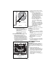
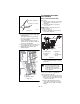
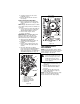
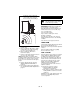
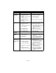
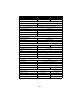
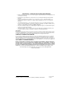
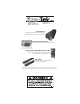
Table Of Contents
GB - 22
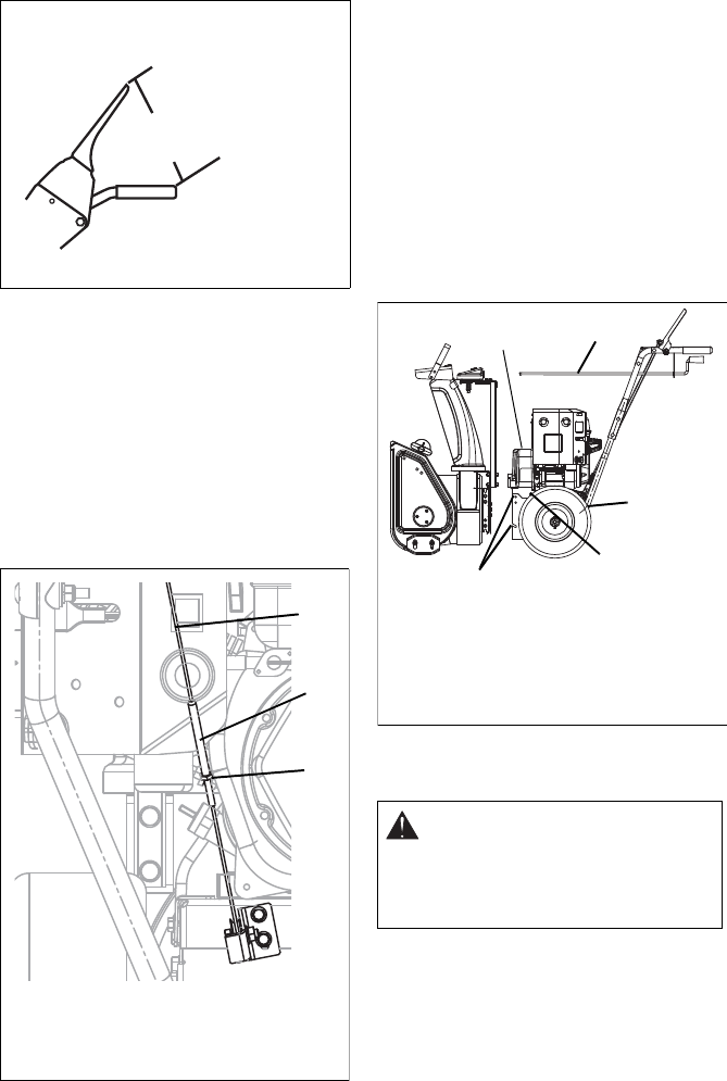
To adjust traction clutch (Figure 24):
1. Loosen jam nut on traction clutch cable
adjustment barrel.
Turn adjustment barrel up the cable to
decrease the distance between clutch
lever and handlebar.
Turn the adjustment barrel down the
cable to increase the distance between
clutch lever and handlebar.
2. Check traction clutch lever distance and
repeat adjustment steps if necessary.
3. Tighten jam nut on traction cable
adjustment barrel.
ATTACHMENT DRIVE BELT
REPLACEMENT
Remove Attachment Drive Belt
(Figure 25)
1. Shut off engine, remove key, disconnect
spark plug wire and allow unit to cool
completely.
2. Loosen the hardware securing belt
cover to unit.
NOTE: DO NOT completely remove the
hardware from unit.
3. Remove belt cover.
4. Remove spring clip from chute crank
and separate (Figure 6).
5. Remove belt fingers by removing cap
screws mounting belt fingers to engine
(Figure 26)
IMPORTANT: To avoid bending bottom cover,
remove the cover before separating the
blower housing from the unit.
6. Support Sno-Tek™ frame and housing.
7. Remove top four cap screws and loosen
lower cap screw holding blower housing
to frame on each side.
8. Remove attachment drive belt from
engine sheave (it may be necessary to
turn engine sheave using recoil starter
handle).
Traction Clutch Lever
OS0458
Figure 23
6-1/8 in. - 6-3/4 in.
(15,5 cm - 17,1 cm)
Figure 24
1. Traction Clutch Cable
2. Jam Nut
3. Adjustment Barrel
1
3
2
CAUTION: Always support
Sno-Tek™ frame and housing
when loosening the cap screws
holding them together. Never
loosen cap screws while unit is in
service position.
Figure 25
1. Chute Crank
2. Belt Cover
3. Bottom
Cover
4. Belt Cover
Screw
5. Housing Bolt
Holes
OS7070
1
3
4
5
2