
Use and Care Manual
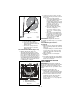
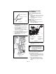
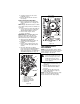
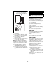
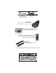
Table Of Contents
GB - 21
2. Adjust cable length (See Figure 21).
a. Loosen jam nut on cable.
b. To increase spring extension,
adjust barrel down the cable and
tighten jam nut.
c. To decrease spring extension,
adjust barrel up the cable and
tighten jam nut.
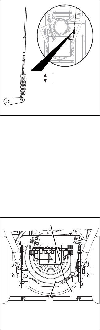
Check Attachment Brake (Figure 22)
1. With the attachment clutch lever
disengaged, brake pad must contact
attachment belt. With attachment clutch
lever engaged, brake pad must be more
than 1/16 in. (1.6 mm) from belt. If there
is more than 1/16 in. (1.6 mm) gap, go to
Check Belt Finger Clearance (Figure 27)
on page 21. If there is less than 1/16 in.
(1.6 mm) gap, go to Step 2.
2. If there is less than 1/16 in. (1.6 mm)
gap between brake pad and belt, follow
these steps:
a. To increase brake pad gap,
loosen idler adjustment nut, and
move idler away from belt.
Position idler to achieve a 1/16 in.
(1.6 mm) minimum brake pad gap
and a 1/2 – 7/8 in. (12.7 –
22.2 mm) gap between the
plastic roller and the frame.
b. Check the clutch cable spring
extension and adjust as
necessary to achieve a 7/16 –
1/2 in. (11.1 – 12.7 mm) spring
extension.
c. If the cable needed adjustment,
recheck gaps described in step 1.
Repeat steps as necessary until
brake clearance, roller gap and
spring extension are within
specified ranges.
IMPORTANT: If adjustments cannot be
brought into specified ranges see your dealer
for repairs.
Check Belt Finger Clearance
(Figure 27)
1. With clutch lever engaged, belt retaining
fingers should be positioned as shown in
Figure 27.
To adjust belt finger, loosen the bolts and
move the finger to the proper position.
Tighten the bolts and recheck the belt
finger clearance.
2. Replace the belt cover and tighten
hardware.
3. Check that auger/impeller stops within 5
seconds after attachment clutch/impeller
brake lever is released.
TRACTION DRIVE CLUTCH
ADJUSTMENT
IMPORTANT: Operating the unit with the
traction drive clutch improperly adjusted will
damage the transmission. Make sure the
clutch is adjusted to the specifications listed
below.
To test traction clutch (Figure 23):
1. Without engine running, push unit
forward while slowly moving the traction
drive clutch lever toward the handlebar.
2. Measure distance between lever and
handlebar when the wheels begin to
brake. If distance is not 6-1/8 in. -
6-3/4 in. (15,5 cm - 17,1 cm), adjust the
traction clutch.
Figure 21
OS8085
7/16 – 1/2 in.
(11.1 – 12.7 mm)
OS7095
Figure 22
OS7085
Minimum of 1/16 in. (1.6 mm) clearance
1. Brake Arm and Pad
2. Attachment Belt Pulley
1
2