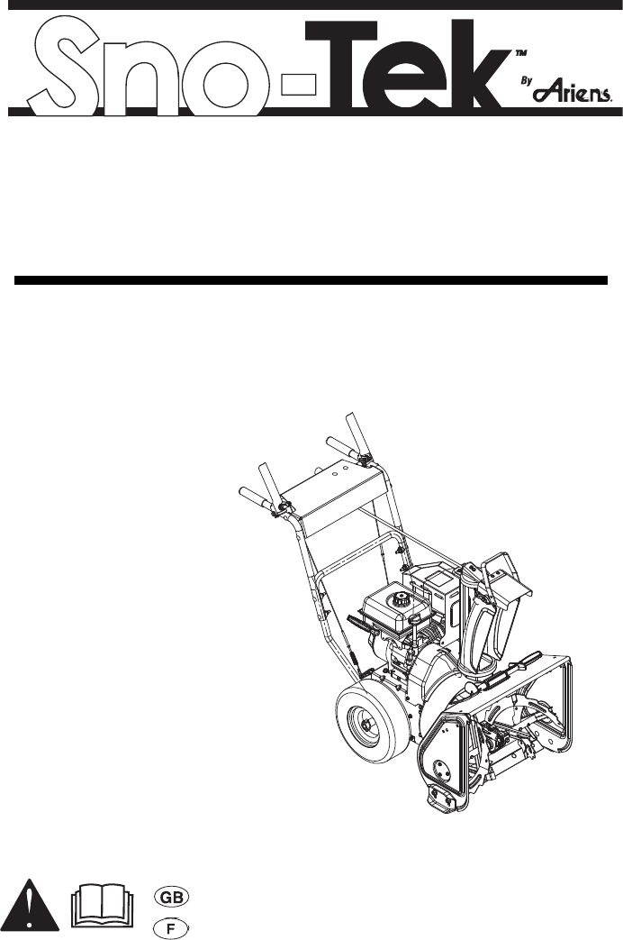
Owner/Operator Manual Manuel Du Propriétaire/Utilisateur Models 939400 – Sno-Tek 22R 939401 – Sno-Tek 20R ENGLISH FRANÇAIS 03883100B 5/10 Printed in USA
TABLE OF CONTENTS SAFETY. . . . . . . . . . . . . . . . . . . . . . . . . . 4 STORAGE . . . . . . . . . . . . . . . . . . . . . . . 24 ASSEMBLY . . . . . . . . . . . . . . . . . . . . . . . 8 SERVICE PARTS . . . . . . . . . . . . . . . . . 25 CONTROLS AND FEATURES . . . . . . . 11 ACCESSORIES. . . . . . . . . . . . . . . . . . . 25 OPERATION . . . . . . . . . . . . . . . . . . . . . 12 TROUBLESHOOTING . . . . . . . . . . . . . 26 MAINTENANCE . . . . . . . . . . . . . . . . . . 16 SPECIFICATIONS . .
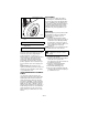
DISCLAIMER Serial Number Label Ariens reserves the right to discontinue, make changes to, and add improvements upon its products at any time without public notice or obligation. The descriptions and specifications contained in this manual were in effect at printing. Equipment described within this manual may be optional. Some illustrations may not be applicable to your unit. DELIVERY Figure 1 OS7005 • Record unit model and serial numbers here. • Record engine model and serial number here.
SAFETY NOTATIONS WARNING: To avoid injury to hands and feet, always disengage clutches, shut off engine, and wait for all movement to stop before unclogging or working on snow thrower. Hand contact with the rotating impeller is the most common cause of injury associated with snow throwers. Never use your hand to clean out the discharge chute. Keep hands and feet away from auger and impeller. NOTE: General reference information for proper operation and maintenance practices.
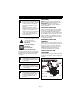
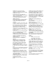
1. WARNING! 3. DANGER! Read owner/operator manual. OL1801 OS2080 OL4370 Keep people away from unit while operating. Keep children out of work area and under watchful care of a responsible adult. Never direct discharge towards persons or property that may be injured or damaged by thrown objects. OL0910 Stop engine, remove key, read manual before making any repairs or adjustments. OL4010 Wear appropriate hearing protection. OL4690 ONLY use clean-out tool to clear blockages. NEVER use your hands. 2.
ALWAYS check overhead and side clearances carefully before operation. ALWAYS be aware of traffic when operating along streets or curbs. Keep children and people away. Keep children out of work area and under watchful care of a responsible adult. NEVER allow children to operate or play on or near unit. Be alert and shut off unit if children enter area. DO NOT allow adults to operate unit without proper training. Only trained adults may operate unit. Training includes actual operation.
Abnormal vibrations are a warning of trouble. Striking a foreign object can damage unit. Immediately stop unit and engine. Remove key and wait for all moving parts to stop. Remove wire from spark plug. Inspect unit and make any necessary repairs before restart. Before cleaning, removing clogs or making any inspections, repairs, etc.: disengage clutch(es), stop unit and engine, remove key, allow moving parts to stop. Allow hot parts to cool.
For extended storage, clean unit thoroughly. See engine manual for proper storage. Use only attachments or accessories designed for your unit. Check components frequently. If worn or damaged, replace with manufacturer’s recommended parts. ASSEMBLY Unfold Handlebar (Figure 4) WARNING: AVOID INJURY. Read and understand the entire Safety section before proceeding. WARNING: Dropping or tipping over boxed unit could result in personal injury or damage to unit. PACKAGE CONTENTS 1.
Install Discharge Chute (Figure 5) Install Discharge Chute Crank (Figure 6) 1. Remove mounting hardware from the bottom of the chute pedestal. 2. Install discharge chute over opening in the auger housing and secure pedestal to auger housing with hardware removed in step 1. 1. Slide chute crank through crank support bracket. NOTE: Be careful not to damage the nylon bushing when sliding crank through bracket. 2. Connect the chute crank to the pinion gear on chute with spring clip pin. 1 3 2 2 3 4 1 1.
Check Tire Pressure Check Auger Gearcase Oil Check tire pressure and adjust to the pressure listed on tire sidewall. Check oil level in auger gearcase (see Check Auger Gearcase on page 17). CAUTION: Avoid injury! Explosive separation of tire and rim parts is possible when they are serviced incorrectly: • Do not attempt to mount a tire without the proper equipment and experience to perform the job. • Do not inflate the tires above the recommended pressure. • Do not weld or heat a wheel and tire assembly.
CONTROLS AND FEATURES 2 1 3 20 5 24 6 13 14 11 12 22 8 7 10 21 9 1. Attachment Clutch Lever 2. Traction Drive Clutch Lever 3. Chute Crank 4. Muffler Guard 5. Discharge Chute Deflector 6. Discharge Chute 7. Impeller 8. Auger 9. Scraper Blade 10. Auger Gearcase 11. Clean-out Tool 12. Oil Fill and Dipstick 13. Gas Tank and Cap 14. Recoil Starter Handle 15. Primer Bulb 16. Oil Drain Plug 17. Ignition Switch (push-pull) 18. Engine Shutoff Switch 19. Choke 20. Spark Plug and Wire 21. Skid Shoes 22.
OPERATION IMPORTANT: If the belt squeals when the attachment clutch lever is engaged, the impeller may be frozen in the auger housing. Immediately release the attachment clutch lever and move the unit into a heated area to thaw. NOTE: If belt squeals when impeller turns freely, see Attachment Clutch/Brake Adjustment on page 19. WARNING: AVOID INJURY. Read and understand the entire Safety section before proceeding.
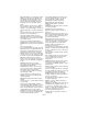
Choke Control Discharge Chute Deflector 1 2 OS1332 1. Choke Closed position: chokes off air to engine for easier start. 2. Choke Open position: allows for normal operation. ALWAYS position discharge chute deflector at a safe angle before starting engine. DO NOT throw snow any higher than necessary. Push deflector handle forward or down to throw snow lower. Pull deflector handle up or to the rear to throw snow higher.
FILLING FUEL TANK PRE-START 1. Frozen Impeller WARNING: AVOID INJURY. Read and understand the entire Safety section before proceeding. GASOLINE Fuel Recommendations Use unleaded gasoline with a pump octane rating of 86 or higher. These engines operate best on unleaded gasoline. IMPORTANT: Before starting engine, check impeller to be sure it is not frozen. To check impeller: 1. With ignition key switch in “Stop” position, squeeze attachment clutch lever to engaged position. 2. Pull recoil starter handle.
NOTE: Try out each control without the engine running to see how it works and what it does. Manual Start 1. Turn discharge chute straight ahead. 2. Make sure that the traction clutch and attachment drive clutch levers are fully disengaged. 3. Push primer bulb 2 or 3 times for cold engine. NOTE: When temperature is below -15° F (-26° C) additional priming may be needed. 4. If engine is cold, apply choke. See engine manual for detailed instructions.
MAINTENANCE Ariens dealers will provide any service or adjustments which may be required to keep your unit operating at peak efficiency. Should engine service be required, contact an Ariens dealer or an authorized engine manufacturer's service center. MAINTENANCE SCHEDULE The chart below shows the recommended maintenance schedule that should be performed on a regular basis. More frequent service may be required. MAINTENANCE SCHEDULE WARNING: AVOID INJURY.
CHECK CLUTCH SPRING ADJUSTMENT Make sure the attachment clutch and traction drive clutch are adjusted to the range specified in Attachment Clutch/Brake Adjustment on page 19 or Traction Drive Clutch Adjustment on page 21. NOTE: Gearcase filler plug may require an application of Loc-Tite® 565 thread sealant with repeated servicing. If Loc-Tite® 565 is not available, use PTFE pipe sealing tape on the filler plug. 1 2 CLEAN ENGINE Refer to engine manual for detailed instructions.
Axle Shaft Grease the axle gear and oil the axle bushings (Figure 13). Oil Grease Figure 13 SERVICE AND ADJUSTMENTS WARNING: AVOID INJURY. Read and understand the entire Safety section before proceeding. SCRAPER BLADE IMPORTANT: Damage to auger/impeller housing will result if blade wears down too far. Scraper blade is adjustable to compensate for wear. To adjust scraper blade: 1. Tip unit back onto handlebar, support housing and loosen nuts retaining blade. 2.
DISCHARGE CHUTE If chute does not stay in position while operating, tighten nut on carriage bolt at pivot point to increase tension on spring (Figure 17). 2 1 2 1. Carriage Bolt 2. Spring 1 1. Auger 2. Shear Bolts Figure 17 Figure 15 DISCHARGE CHUTE DEFLECTOR ATTACHMENT CLUTCH/BRAKE ADJUSTMENT Deflector must stay in selected position while throwing snow. To adjust, loosen then retighten the wing knob to desired tension (Figure 16).
Check Attachment Idler Arm Roller Clearance 1 1. Place the unit into the service position. Remove the bottom cover. 2. With the clutch lever engaged, check the clearance between the frame and plastic roller on the lower end of the attachment idler arm. See Figure 20. 2 3 Roller OS7090 1. Attachment Clutch Cable 2. Cable Adjustment Barrel 3. Jam Nut Figure 18 Roller should be 1/2 – 7/8 in. (12.7 – 22.2 mm) from the frame when the attachment clutch is engaged. 5.
7/16 – 1/2 in. (11.1 – 12.7 mm) OS7095 OS8085 Figure 21 2. Adjust cable length (See Figure 21). a. Loosen jam nut on cable. b. To increase spring extension, adjust barrel down the cable and tighten jam nut. c. To decrease spring extension, adjust barrel up the cable and tighten jam nut. 2. If there is less than 1/16 in. (1.6 mm) gap between brake pad and belt, follow these steps: a. To increase brake pad gap, loosen idler adjustment nut, and move idler away from belt.
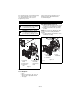
ATTACHMENT DRIVE BELT REPLACEMENT Traction Clutch Lever Remove Attachment Drive Belt (Figure 25) 1. Shut off engine, remove key, disconnect spark plug wire and allow unit to cool completely. 2. Loosen the hardware securing belt cover to unit. NOTE: DO NOT completely remove the hardware from unit. 3. Remove belt cover. 4. Remove spring clip from chute crank and separate (Figure 6). 6-1/8 in. - 6-3/4 in. (15,5 cm - 17,1 cm) OS0458 Figure 23 To adjust traction clutch (Figure 24): 1.
9. Separate housing from unit. Lower handlebar on floor. 10. Remove attachment drive belt from lower pulley. 1/8 to 3/16 in. (3.2–4.8 mm) 2 Replace Attachment Drive Belt 1. Place new belt onto lower pulley and while holding brake out of way, tip unit together. NOTE: Engage attachment clutch lever while connecting housing to frame to hold brake out of the way. 2. Secure blower housing to frame with cap screws removed in step 7 of Remove Attachment Drive Belt on page 22. 3. Place belt onto engine sheave. 4.
Position the traction drive belt on the engine sheave like this when removing and installing it. STORAGE WARNING: AVOID INJURY. Read and understand the entire Safety section before proceeding. SHORT TERM IMPORTANT: NEVER spray unit with high pressure water or store unit outdoors. Run with attachment clutch engaged a few minutes after each use to free unit of any loose or melting snow. Close fuel shut-off valve. Inspect unit for visible signs of wear, breakage or damage.
SERVICE PARTS Order the following parts through your dealer: Part No. Description 00036800 Ariens Hi-Temp Grease (3, 3 oz. cartridges) ACCESSORIES See your authorized Ariens dealer to add the additional accessories available to your Sno-Tek™. Part No. Description 72000200 Slicer Bar 21547400 Spark Plug 72600300 Composite Skid Shoe Kit 07200108 Impeller Belt 73203600 Cover 07200109 Stretch Fit Traction Belt 53200500 Shear Bolts 00592900 Gas Stabilizer (4 oz.
TROUBLESHOOTING PROBLEM Engine will not crank/start. PROBABLE CAUSE CORRECTION 1. Fuel tank is empty. 2. Fuel shut-off valve is closed. 3. Build up of dirt and residue around governor/carburetor. 4. Key switch not in run position. 5. Engine shut off switch turned off. 1. Fill fuel tank. 2. Open fuel shut-off valve. 1. Out of fuel. 2. Fuel shut-off valve is closed. 3. Mechanical jam in blower rake or impeller. 4. Polluted fuel supply. 5. Faulty spark plug. 6. Plugged fuel cap vent. 1. Fill fuel tank.
SPECIFICATIONS Model Number Description 939400 939401 Sno-Tek™ 22 Sno-Tek™ 20 Engine Engine Model LCT Storm Force Gross Torque* - ft-lbs (N-m) 9.5 (12.9) *Engine output stated in gross torque per SAE J1940 as rated by engine manufacturer Displacement - in. (cc) 12.7 (208) High Idle - RPM (min) 3600 ± 50 Start Recoil Fuel Tank Capacity - qt (Liters) 3.8 (3.6) Chute Chute Rotation Angle 205° Rotation Control 2.5X Quick Turn Deflector Control Manual Auger Snow Clearing Width - in.
Sno-Tek™ Two-Year Limited Warranty Ariens Company (Ariens) warrants to the original purchaser that Sno-Tek brand products will be free from defects in material and workmanship for a period of two years after the date of purchase. An authorized Ariens dealer will repair any defect in material or workmanship, and repair or replace any defective part, subject to the conditions, limitations and exclusions set forth herein.
Exclusions – Items Not Covered by This Warranty • • • • • • Engines and engine accessories are covered only by the engine manufacturer’s warranty and are not covered by this warranty. Parts that are not genuine Ariens service parts are not covered by this warranty and may void the warranty. Damages resulting from the installation or use of any part, accessory or attachment which is not approved by the Ariens Company for use with product(s) identified herein are not covered by this warranty.
Ariens Company 655 West Ryan Street Brillion, WI 54110-1072 920-756-2141 www.ariens.com Sno-Tek Cover Waterproof, washable and tear-resistant, this cover protects your Sno-Tek when it is not in use. Non-Abrasive Skid Shoes Protect the decorative surfaces around your home. Sno-Tek LCT® Engine Maintenance Kit Includes Ariens 32oz. 5W30 engine oil, Spark Plug, Fuel stabilizer and a spare ignition key. Drift Cutter Extend the bars to cut through drifts and direct snow into the auger.