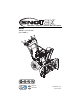
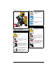
Operator’s Manual | Manuel de l'utilisateur Model 920402 – Sno-Tek 24E (SN 175000 +) E10 ENGLISH FRANÇAIS 04854200A • 6/15 Printed in USA
TABLE OF CONTENTS WELCOME . . . . . . . . . . . . . . . . . . . . . . 1 ADJUSTMENTS . . . . . . . . . . . . . . . . . . 14 SAFETY . . . . . . . . . . . . . . . . . . . . . . . . 2 Adjust Scraper Blade. . . . . . . . . . . . . . . Adjust Skid Shoes . . . . . . . . . . . . . . . . . Replace Shear bolts . . . . . . . . . . . . . . . Adjust Discharge Chute Deflector Lever . . . . . . . . . . . . . . . . . . . . . . . . . . Adjust Discharge Chute. . . . . . . . . . . . . Adjust Speed Selector Lever. . . . . .
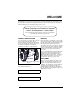
WELCOME Congratulations on your purchase and welcome to the Ariens family! Every snow thrower in the Ariens lineup is designed for long-lasting and unsurpassed performance. We are confident your machine will be part of your family for many years to come. Have Questions or Need Assistance? ariens.custhelp.com • ariens.com A service guide and a parts manual for your unit are available for free download or purchase at ariens.com.
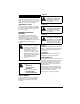
1. Danger SAFETY DANGER: Indicates an IMMINENTLY HAZARDOUS SITUATION! If not avoided, WILL RESULT in death or serious injury. Read these safety rules and follow them closely. Failure to follow these rules could lead to loss of control of unit, severe personal injury or death to you or bystanders, or result in damage to property or the machine. 2. Warning PRACTICES & LAWS Practice usual and customary safe working precautions. Learn applicable rules and laws in your area.
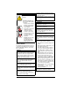
Safety Decal Locations Stop engine, remove key, and read manual before making any repairs or adjustments. 1 2 Read operator’s manual. Wear appropriate hearing protection. 3 2. DANGER! Figure 2 Safety Decal Descriptions Danger! 1. CAUTION! Danger! ROTATING PARTS! Only use clean-out tool to clear blockages. NEVER use your hands. Only use clean-out tool to clear blockages. NEVER use your hands. NEVER direct discharge towards persons or property that may be injured or damaged by thrown objects.
Complete a walk-around inspection of the unit to understand the unit, your work area and all safety decals. 3. DANGER! Understand how to operate all controls, the functions of all controls and how to STOP in an emergency. Danger! ROTATING PARTS! Keep clear of auger while engine is running. • Read operator’s manual. • Allow operation only by properly-trained adult, never children. • Stop engine and remove ignition key prior to leaving the operator’s position for any reason.
Never attempt to make any adjustments while the engine is running (except when specifically recommended by manufacturer). Always allow unit and engine to adjust to outdoor temperature before clearing snow. Do not run the engine indoors, except when starting the engine and for transporting the snow thrower in or out of the building. Open the outside doors; exhaust fumes are dangerous. Operation Never operate the snow thrower without proper guards, and other safety protective devices in place and working.
Avoid contact with sharp edges; sharp edges can cut. Always refer to operator's manual for important details if the snow thrower is to be stored for an extended period. Do not throw snow higher than necessary. Maintain or replace safety and instruction labels as necessary. Clearing a Clogged Discharge Chute Hand contact with the rotating auger / impeller inside the discharge chute is the most common cause of injury associated with snow throwers. Never use your hand to clean out the discharge chute.
Fuel DO NOT run engine in an enclosed area. Always provide good ventilation. Fumes from engine exhaust can cause injury or death. Fuel is highly flammable and its vapors are explosive. Handle with care. Use only an approved gasoline container with an appropriately-sized dispensing spout. No smoking, no sparks, no flames. Always allow engine to cool before servicing. Never fill fuel tank when engine is running or hot from operation. Never fill or drain fuel tank indoors.
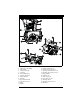
CONTROLS & FEATURES 24 23 22 25 25 12 21 4 13 7 20 8 14 19 2 6 3 18 5 1 16 10 11 9 15 17 Figure 3 1. 2. 3. 4. 5. 6. 7. 8. 9. 10. 11. 12. 13. Engine Key Engine Run / Stop Switch Primer Bulb Fuel Tank and Cap Fuel Valve Electric Start Button Choke Control Knob Oil Fill / Dipstick Oil Drain Recoil Starter Handle Speed Selector Lever Auger Impeller 14. 15. 16. 17. 18. 19. 20. 21. 22. 23. 24. 25.
CHOKE CONTROL KNOB WARNING: Read and understand the Safety section before proceeding. See Figure 6. Controls airflow to the engine. Off See Figure 3 for all controls and features locations. ENGINE KEY AND RUN / STOP SWITCH On See Figure 4. The removable engine key and the run / stop switch are used together to start the engine. The engine key must be inserted and in the run position for engine to start. Figure 6 SPEED SELECTOR LEVER See Figure 7. Controls the speed of forward and reverse travel.
TRACTION DRIVE CLUTCH LEVER (LEFT SIDE) See Figure 9. Allows unit to travel forward and in reverse. Figure 11 Figure 9 SCRAPER BLADE DUAL HANDLE INTERLOCK Allows auger / impeller to rotate without holding attachment clutch lever continuously. Auger continues to turn until both clutch levers are released. Contacts the surface being cleared and protects the housing from damage during normal use. SKID SHOE Controls the distance between the scraper blade and the surface.
2. Check fuel level and add fuel if needed. OPERATE UNIT IMPORTANT: Use fresh unleaded fuel with an octane rating of at least 87. DO NOT use E85 blended fuels; the engine is not E20 / E30 / E85 compatible. The maximum recommended ethanol content is 10%. 1. Rotate discharge chute and move deflector to desired positions. 2. Select desired speed. 3. Engage attachment clutch. 3. Check engine oil level and add oil if needed. Refer to engine manual. 4. Check function of controls.
Your Ariens dealer can provide service and adjustments to keep your unit operating at peak efficiency. Contact an authorized engine manufacturer’s service center for engine service. • • Annually Every 25 hrs. Service Performed Every 5 hrs. WARNING: Read and understand the Safety section before proceeding.
CHECK FASTENERS 2 Check for loose hardware. CHECK CLUTCH CABLE ADJUSTMENTS 3 Auger / impeller must stop within 5 seconds when attachment clutch lever is released. Wheels must stop quickly when traction drive clutch lever is released. If clutches do not engage or disengage correctly, see Adjust Attachment Clutch & Brake on page 16 or Adjust Traction Drive Clutch on page 18. Refer to the service guide for your unit for more information about clutch repairs.
Auger Shaft Use the following key for all lubrication procedures. Grease Oil * = Lubricate on Both Sides Traction Drive 1. Place unit in service position (see Figure 13) and remove bottom cover. 2. Lubricate as shown in Figures 15 and 16. See Figure 17. 1. Remove shear bolt nuts and bolts. 2. Apply grease at the grease zerks. 3. Hand rotate auger on auger shaft. 4. Align shear bolt holes in auger with shear bolt holes in shaft. 5. Insert bolts through holes. 6. Secure bolts with nuts. 7.
3. Adjust skid shoes. See Adjust Skid Shoes on page 15. NOTICE: ALWAYS adjust skid shoes after adjusting blade to prevent premature wear of blade and auger housing damage. ADJUST SKID SHOES To adjust skid shoes: 1. Place unit on a hard, flat surface. 2. Insert a spacer under the center of scraper blade. • Use a 3 mm (1/8") spacer for hard, smooth surfaces. • Use a 22 mm (7/8") spacer for uneven or gravel surfaces. 3. Loosen skid shoe hardware and slide skid shoes to flat surface. Adjust both shoes equally.
ADJUST DISCHARGE CHUTE 3 See Figure 20. If discharge chute does not stay in selected position, tighten nut on carriage bolt. 4 1 2 1. 2. 3. 4. Figure 20 Shift Rod Adjustment Pivot Pin Speed Selector Arm Hairpin Figure 21 ADJUST ATTACHMENT CLUTCH & BRAKE ADJUST SPEED SELECTOR LEVER See Figure 21. 1. Disconnect adjustment pivot pin from speed selector arm. Save hardware for reinstallation. 2. Position speed selector lever in fastest forward position. 3. Turn speed selector arm down as far as it will go.
6. Tighten jam nut on cable adjustment barrel. See Figure 22. 7. Reinstall belt cover and tighten hardware. 8. Reconnect spark plug wire. Check Attachment Idler Arm Roller Clearance 1. Place unit in service position and remove bottom cover. 2. Engage attachment clutch and check the clearance between the frame and plastic roller on the lower end of the attachment idler arm. Roller should be 12.7 – 22.2 mm (1/2 – 7/8") from the frame. See Figure 24. 1 2 3 Measure here. 1. Attachment Clutch Cable 2.
Check Belt Finger Clearance See Figure 27. With attachment clutch engaged, the belt finger located opposite the belt idler must be less than 3.2 mm (1/8") from belt, but must not touch the belt. To adjust belt finger: 1. Remove belt cover. 2. Loosen bolts and move belt finger to correct position. 3. Tighten bolts and recheck belt finger clearance. 4. Replace belt cover and tighten hardware. 1 2 1. Attachment Belt Idler 2.
3. Loosen jam nut on traction cable adjustment barrel, and then turn adjustment barrel down to shorten cable and remove cable slack. 2 1 1 2 3 1. Swing Gate Tab 2. Stop Hole Figure 29 5. Reconnect spark plug wire. 1. Traction Drive Clutch Cable 2. Cable Adjustment Barrel 3. Jam Nut Figure 28 4. With traction clutch disengaged, check that swing gate tab touches the front edge of stop hole. See Figure 29. IMPORTANT: Swing gate tab MUST touch side of stop hole.
TROUBLESHOOTING Problem Probable Cause Engine switch is in off position. Engine key is not in unit. Choke is off. Fuel valve is closed. Fuel tank is empty. Engine is not primed. Correction Push switch to on position. See Start The Engine on page 11. Insert key. See Start The Engine on page 11. Turn choke control knob to on position. See Start The Engine on page 11. Open valve. See Fuel Valve on page 9. Fill tank with fuel. See Before Operating Unit on page 10.
TROUBLESHOOTING Problem Probable Cause Friction disc is worn. Correction Replace friction disc. Refer to the service guide for your unit. Traction drive cable is not Remove slack from cable. See Adjust Unit does not adjusted correctly. Traction Drive Clutch on page 18. drive forward or Traction belt is not functioning. Repair or replace traction drive belt. Refer in reverse. to the service guide for your unit. Speed selector is not adjusted Adjust speed selector. See Adjust Speed correctly.
5. Remove weight from wheels by putting blocks under frame or axle. 6. Store unit in a cool, dry, protected area. Do not store unit outdoors. STORAGE WARNING: AVOID INJURY. Read and understand the Safety section before proceeding. SHORT TERM 1. Run auger / impeller for a few minutes to remove loose or melting snow to prevent impeller from freezing. 2. Tighten all hardware to correct specifications. 3. Inspect unit for visible signs of wear or damage. Repair as needed. 4.
SPECIFICATIONS Model Number 920402 Description Sno-Tek 24E Engine LCT Storm Force Gross Torque* – N•m (lbf-ft) 12.8 (9.5) Displacement – cm3 (in3) 208 (12.7) High Idle – RPM (min) 3600 ± 100 Electric Start 120V Fuel Tank Capacity – liter (qt) 2.7 (2.9) Chute Chute Rotation Angle 205° Rotation Control 2.5X Quick Turn Deflector Control In-dash Lever Auger Snow Clearing Width – cm (in) 61.0 (24.0) Gearcase Aluminum Auger Diameter – cm (in) 27.9 (11.
Sno-Thro®, Sno-Tek® and Chore Performing Equipment Limited Warranty Warranty Ariens Company (Ariens) warrants to the original purchaser that Ariens, Gravely, Parker, and Countax ® ® brand chore performing equipment (including Sno-Thro and Sno-Tek equipment) purchased on or after 1/1/2015 will be free from defects in material and workmanship for the time period noted in the chart below.
Exceptions and Limitations The chart below details special exceptions to this warranty: Warranty Code Warranty Period Use 1 Year All None Commercial These components are not covered when used commercially. Maximum 2 Years All Warranty is limited to 2 years for consumer use. (1 year for warranty code "PD".) Except as noted above, these components are covered for defect, not for wear. Maximum 2 Years All Warranty is limited on idlers to 2 years for consumer use.
Exclusions – Items Not Covered by This Warranty • Parts that are not genuine Ariens, Gravely, Parker or Countax service parts are not covered by this warranty and may void the warranty. • Damages resulting from the installation or use of any part, accessory, or attachment which is not approved by the Ariens Company for use with product(s) identified herein are not covered by this warranty.
655 West Ryan Street Brillion, WI 54110 ariensco.com ariens.