OPERATOR’S MANUAL Chipper / Shredder 5/14 Series Mfg. No. 1694910 1694898 7085637 7800070 Description Model 5/14, 5.5HP Simplicity Chipper / Shredder Model 5/14, 5.5HP Simplicity Chipper / Shredder (CE) Model SAC55140BV, 5.5HP Snapper Chipper / Shredder Model E55140BV, 5.5HP Snapper Chipper / Shredder (CE) 8/14 Series Mfg. No. 1694678 Description Model 8/14, 8HP Simplicity Chipper / Shredder Manual No. 1732150 Revision 00 Rev.
Table of Contents Safety Rules & Information.................................2 Troubleshooting & Repair.................................17 Safety Decals ..........................................................6 Safety Icons ............................................................7 Identification Numbers ............................................8 Troubleshooting Chart ..........................................17 Repair ...................................................................
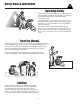
Safety Rules & Information Operating Safety Congratulations on purchasing a superior-quality piece of lawn and garden equipment. Our products are designed and manufactured to meet or exceed all industry standards for safety. Power equipment is only as safe as the operator. If it is misused, or not properly maintained, it can be dangerous! Remember, you are responsible for your safety and that of those around you. Use common sense, and think through what you are doing.
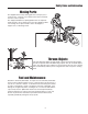
Safety Rules and Information Moving Parts This equipment has many moving parts that can injure you or someone else. However, if you follow all the rules in this book, the unit is safe to operate. The chipper/shredder has spinning blades that can amputate hands and feet. Do not allow anyone near the equipment while it is running! Do not place hands or feet in the hopper or chipper cone, or discharge chute. Thrown Objects This unit discharges debris at high speeds.
Safety Rules & Information Read these safety rules and follow them closely. Failure to obey these rules could result in loss of control of unit, severe personal injury or death to you, or bystanders, or damage to property or equipment. This unit is capable of amputating hands and feet and throwing objects. The triangle in text signifies important cautions or warnings which must be followed. PREPARATION 15. Always maintain secure footing and solid balance while starting or operating the chipper/shredder.
Safety Rules and Information 28. Use only attachments and accessories approved of by the manufacturer or the machine. 8. Keep nozzle in contact with the rim of the fuel tank or container opening at all times until fueling is complete. Do not use a nozzle lock-open device. 9. If fuel is spilled on clothing, change clothing immediately. 10. Never over-fill the fuel tank. Replace gas cap and tighten securely. 11. Use extra care in handling gasoline and other fuels. They are flammable and vapors are explosive.
Safety Decals Safety Decals All DANGER, WARNING, CAUTION and instructional messages on your unit should be carefully read and obeyed. Personal bodily injury can result when these instructions are not followed. The information is for your safety and it is important! The safety decals below are on your unit. This unit has been designed and manufactured to provide you with the safety and reliability you would expect from an industry leader in outdoor power equipment manufacturing.
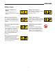
Safety Icons Safety Icons Warning: Read Operator’s Manual. Danger: Thrown Objects. This machine is capable of throwing objects and debris. Keep bystanders away. Read and understand the Operator’s Manual before using this machine. Danger: Amputation Hazard. Danger: Thrown Objects. To avoid serious personal injury from rotating cutting blades, keep hands out of inlet while machine is running. This machine is capable of throwing objects and debris. Keep bystanders and children away when engine is running.
Identification Numbers SA M North American / CE Models PL E SA M CE Models (Only) ID Tag PL PRODUCT REFERENCE DATA E Model Description Name/Number When contacting your authorized dealer for replacement parts, service, or information you MUST have these numbers. Record your model name/number, manufacturer’s identification numbers, and engine serial numbers in the space provided for easy access. These numbers can be found in the locations shown.
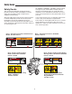
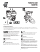
Features and Controls Figure 1. Controls Control Functions The information below briefly describes the function of individual controls. Operating requires the combined use of several controls applied in specific sequences. To learn what combination and sequence of controls to use for various tasks see the OPERATION section. Engine Stop / Throttle Control Choke The engine stop / throttle control lever controls turn the engine off and controls the engine speed.
Operation General Operating Safety DANGER Be sure to read all information in the Safety and Operation sections before attempting to operate this unit. Become familiar with all of the controls and how to stop the unit. The exhaust from this product contains carbon monoxide gas. Carbon monoxide is a colorless, orderless, and tasteless gas that can cause dizziness, nausea, unconsciousness, or even brain damage and death if inhaled for prolonged periods.
Operation Stopping the Engine NOTE: In the event of an emergency the engine can be stopped by setting the throttle control to STOP. 1. Slide the throttle control fully left to the STOP position. NOTE: Upon start-up and shut-down, you may hear the metal-to-metal sound of the triangular hammers and Jhammers positioning themselves on the rotor. This is normal. 2. After the engine has stopped moving, remove the spark plug wire and remove any debris from the unit and engine.
Operation Chipping & Shredding Recommendations Operation Type of Waste Permitted Size Limitations Notes Shredding Dry or moist organic material including leaves, plants, flowers, fruits, or vegetables. Branches and twigs up to 1/2” diameter and 18” long. Alternately chip or shred moist green waste with dry waste to avoid plugging of the discharge chute. Long, thicker tree limbs or small bunches of smaller sticks grouped together for ease of handling.
Regular Maintenance Maintenance Schedule & Procedures The following schedule should be followed for normal care of your unit. SAFETY ITEMS Before Every 5 Every 25 Every Each Hours Hours 100 Use Hours Check for loose hardware Every 250 Hours • Spring & Fall • Check all safety labels • Inspect cone, hopper, and guards. • CHIPPER MAINTENANCE ITEMS Clean debris from engine and chipper.
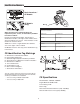
Regular Maintenance A Figure 4. Clean Debris from Engine Cooling Fins Figure 5. Inspect Shredder Hammers A. Access Panel Clean Debris from Engine & Chipper Service Interval: Before each use and every 100 hours. The engine requires air flow to cool itself and for combustion. Before each use, clean any debris from the unit especially from around the air shroud intake, air filter, and muffler.
Regular Maintenance Inspect Chipping Knives Service Interval: Every 25 Hours, or As Necessary The chipping knives of this unit can be rotated or sharpened to provide a new cutting surface as required. When inspecting the knives be careful to avoid touching the sharpened edges. To inspect the chipping knives: 1. Disconnect the spark plug wire and secure it away from the spark plug.
Regular Maintenance Engine Oil Type & Capacity Use oil classified API Service Class SF, SG, SH, SJ or better with SAE Viscosity: Select a quality engine oil using the chart in Figure 10. 5.5 HP models require 5/8 quart (0.6L) of oil. 8HP models require 7/8 quart (0.8L) of oil. 30 Conventional** Check Engine Oil Level 5W-30 10W-30 Conventional* Service Interval: Before Each Use Check the engine oil level at the oil fill and level check plug (A, Figure 11). 5W-30, 10W-30 Synthetic 1.
Troubleshooting & Repair Troubleshooting Chart WARNING While normal care and regular maintenance will extend the life of your equipment, prolonged or constant use may eventually require that service be performed to allow it to continue operating properly. To avoid serious injury, perform maintenance on the unit only when the engine is stopped. Always disconnect the spark plug wire and fasten it away from the plug before beginning the maintenance, to prevent accidental starting of the engine.
Troubleshooting & Repair Figure 12. Removing the Shredder Hopper Figure 13. Removing the Rotor Housing Repair F E Shredding Hammer Rotation and Replacement G The cutting edges of the shredding hammers may eventually wear out requiring rotation of the hammer or replacement if all cutting edges have been dulled. Triangular hammers can be rotated twice after the first edge dulls, then flipped over once and rotated again for a total of 6 edges.
Troubleshooting & Repair Chipping Knives Sharpening and Replacement The chipping knives should be sharpened or replaced when tree limbs require extra force to feed into the chipper cone. The chipping knives may be resharpened at a 30 degree angle until the distance between the edge of the blade bevel and the mounting hole is less than 1/16” (1,6mm) (see Figure 17). To inspect, sharpen, or replace the chipping knives: Figure 15. Installing the Chipper Cone 1.
Initial Assembly D A Figure 19. Attaching the Hopper C B Figure 18. Installing the Chipper Cone A. 1/4-20 x 3/4 Screw, Washer, & Nut B. 5/16-18 Flange Nut C. Cone Base D. Chipper Cone Initial Assembly Install Chipper Cone - All Models 1. Secure the chipper cone (D, Figure 18) to the chipper cone base (C) using 1/4-20 x 3/4 screws, washers, and nuts (A). Figure 20. Installing Hardware Inside the Hopper 2.
Initial Assembly Install the Handle - All Models 1. Lift the hopper handle up until the outer holes in the handle align with the holes in the shredder hopper and secure with 1/4-20 x 3/4 screws, washers, and nuts (A, Figure 21). Insert the screws from the outside of the shredder hopper. A Figure 21. Installing the Hopper Handle A.
Initial Assembly Slide bag over discharge chute. Make sure bag noose fits over top of discharge chute and notch in chute bottom. Lift discharge chute and slide bag over chute. Make sure bag noose fits over top of discharge chute and notch in chute bottom. Pull drawstring tight. Pull drawstring tight. Figure 22. Discharge Bag - North American Models Figure 23.
Specifications NOTE: Specifications are correct at time of printing and are subject to change without notice. * Actual sustained equipment horsepower will likely be lower due to operating limitations and environmental factors. ENGINE: CHASSIS: 5.5 HP* Briggs & Stratton All Models Make Model Horsepower Displacement Oil Capacity Chipping Capacity Shredding Capacity Chipping Knives Shredding Hammers Briggs & Stratton 120000 5.5 @ 3600 rpm 12.48Cu. in (206 cc) 20 Oz. (.
Parts & Accessories Replacement Parts Technical Manuals Replacement parts are available from your authorized dealer. Always use genuine Simplicity/Snapper Service Parts. Additional copies of this manual are available, as well as fully illustrated parts lists. These manuals show all of the product’s components in exploded views (3D illustrations which show the relationship of parts and how they go together) as well as part numbers and quantities used.
MANUFACTURING, INC. 500 N Spring Street / PO Box 997 Port Washington, WI 53074-0997 www.SimplicityMfg.com Simplicity Mfg. Inc. - Snapper division 535 Macon Street McDonough, GA 30253 www.Snapper.com © Copyright 2005 Simplicity Manufacturing, Inc. All Rights Reserved. Printed in USA.