
Manual


3. Some models have gauge wheels on the mower deck. If
equipped, removethe gauge wheels.
4. Move the decklift lever to the LEVELADJUSTMENT
position (Figure 39).
,_ WARNING:The decklift lever is spring loaded.Makesure the lift lever is locked inthe LEVEL
ADJUSTMENTposition.
5. Loosen the left and right adjuster knobs(Figure 40).
Push down on each side of the mower deck. Make sure
both sides of the mower deck are setting on a flat
surface. Also, make sure the lift links are loose and can
easily move up or down.
6. Pushdown on the lift links and tighten the left and
right adjusterknobs(Figure 40). Make sure the
adjusterknobsaretight. If necessary, use a wrench to
tighten the adjusterknobs.For plastic adjusterknobs,
tighten to a torque of 7 foot pounds (9,5 Nm). For
metal adjusterknobs,tighten to a torque of 10 foot
pounds (13,5 Nm).
7. Raisethe deck lift lever from the LEVELADJUSTMENT
position to a CUTTINGHEIGHTposition (Figure 41).
8. If equipped, install the gaugewheels.
9. Mow for a short distance. If the height of cut is not
level, repeat the above steps.
CAUTION:Do notoperatewith the mowerdeck in the
LEVELADJUSTMENTposition.If youoperate in the LEVEL
ADJUSTMENTposition,the mowerdeck and blades canbe
damaged.
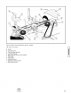
Figure 39: Lever adjustment
A - Deck lift lever
B - LEVELADJUSTMENTpositon
C - CUTTINGHEIGHTpositions
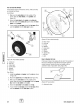
Figure 40: Loosening adjuster knobs
A - Lift rink
B - Adjuster knobs
Figure 41: Cutting position
A - Deck rift lever
B - CUTTINGHEIGHTpositions
Replacingthe Motion Drive Belt
The motion drive belt is designed for extremely long life, and
with proper care and maintenance,it should last for the life
of the unit. However,in the unlikely eventthat the motion
drive belt should require replacement,it should be
performed only by an authorizeddealer.
,-,z
English
33