
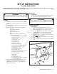
Install Drawing


ELECTRICAL CIRCUIT
The electrical connection at the engine is shipped disconnected to
protect the electrical system when the battery is installed and MUST
BE THE LAST STEP in preparation.
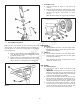
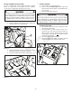
A. Connect the electrical circuit at the rear of the engine
(Figure 22). NOTE: Typical Briggs engine pictured.
LUBRICATION and FUEL
1. Engine
A. Perform normal engine service, oil and fuel, according
to the engine manufacturer’s recommendations found in the
Engine Owner’s Manual.
PRE-OPERATION CHECKLIST
Complete all items on the Pre-Operation Checklist as instructed.
A
Figure 21
Figure 22
6
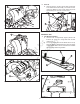
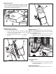
DISCHARGE DEFLECTOR
The discharge deflector (A, Figure 19) on some models is shipped
in the “UP” position. Remove the rubber band, lower the discharge
deflector, and secure to the deck with the carriage bolts, flat wash-
ers, and wing nuts (B) furnished in the deck.
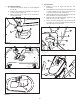
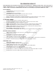
WATER BOTTLE (not all models)
1. Water Bottle Holder Installation
A. Attach the water bottle holder (A, Figure 20) to the right
side of the steering column with two hex washer self-
tapping screws (B). Tighten securely.
B. Insert the water bottle (A, Figure 21, next page) into
the holder.
B
A
B
Figure 19
A
Figure 20
B
Not for
Reproduction