
Install Drawing
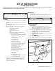


SET-UP INSTRUCTIONS
For REAR ENGINE RIDERS
The following instructions cover the set-up of the Rear Engine Rider. The unit is shipped with steering, fuel tank, and seat assemblies
detached. Complete each of the following steps carefully.
UNCRATING
1. Remove the top and side crating, parts boxes, literature
package, and all packing materials from in and around
the unit.
2. Carefully cut and remove the bands securing the unit to
the crate bottom.
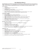
3. Open the parts boxes and identify the components:
Fuel tank
Canister/holder assembly
Steering wheel
Foam steering shaft cover
Seat
Water bottle and holder (not all models)
Hardware bag containing:
1 - Thrust bushing, 5/8” ID x 1-5/16” OD
1 - Cotter pin, 3/16 x 1”
1 - Bushing cover
1 - Roll pin, 1/4 x 1-1/2”
2 - Tie rod bushings
2 - Flat washers, 3/8”
2 - Cotter pins, 5/32 x 1”
2 - Differential grease plugs
2 - Torx screws, self-tapping, 1/4 x 1/2”
1 - Clamp, fuel vent hose
2 - Seat brackets
4 - Carriage bolts, 5/16 x 1”
4 - Bolt retainers, 5/16
4 - Flange screws, self-tapping, 5/16 x 1/2”
2 - Center lock flange nuts, 5/16”
2 - Seat knob spacers
2- Seat knobs
1- Seat switch
2 - Center lock nuts, 1/4”
2 - Self-tapping screw, #10 x 1/2” (models
with water bottle only)
4. Carefully stand the machine on its rear bumper, and
remove the crate bottom from the assembly area.
NOTE: Keep the machine on its rear bumper during the
next few assembly steps.
MOWING DECK
1. Cutting Blade
A. Check the torque of the blade mounting bolts - 50 ft. lbs.
B. Check blade straightness per operator’s manual.
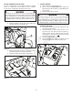
STEERING COMPONENTS
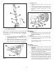
1. Steering Shaft
A. Push the steering shaft (A, Figure 1) into place.
NOTE: Some units may have a wire tie securing the
steering shaft in place. If so, remove the wire tie.
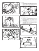
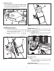
B. Tap the upper bushing (B, Figure 2 (next page),
installed) so that it contacts the control panel (A).
C. Place the thrust washer (C) on top of the bushing.
D. Install the 3/16” x 1” cotter-pin (D) into the steering
shaft above the thrust washer.
E. Install the bushing cover (E) over the cotter-pin, thrust
washer and bushing.
F. Slide the foam steering shaft cover (F) over the steering
shaft.
INSTRUCTION No. 7104957 (Rev. ‘A’)
1
WARNING
Do not attempt to start or operate this unit until all assembly
steps have been completed. Serious injury or equipment damage
may result.
WARNING
Wear heavy leather gloves when handling or working around
cutting blades. Blades are extremely sharp and can cause severe
injury.
!
!
!
!
Figure 1
D
E
C
A
B
Not for
Reproduction