
Manual


Maintenance(Continued)
WARNING
DONOTattempt any adjustments, maintenance,service or
repairs with the engine running. Stop engine.Stop blade.
Engageparking brake. Remove key. Remove spark plug
wire from spark plug and secureaway from plug. Engine
and components are HOT.Avoid serious burns, allow all
parts to cool before working on machine. Fuel Filler Cap
and Vent must be closed securely to prevent fuel spillage.
DONOTattempt to service or charge the battery while it is
installed on the machine.
Battery
Battery Removal
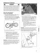
1. Carefullypull each side of the battery cover (A, Figure
48) away from the ratchetfasteners (B) and removethe
cover.
Figure 48. Removing the battery cover
2. Removethe hair pin and swivel from the deck support
to allow clearancefor battery removal.
3. Slide the battery from the battery box to gain accessto
the terminal cables.
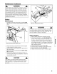
4. Observeand note the cable positions (A and B, Figure
49) on the battery.
5. Disconnectthe cablesfrom the battery terminals, dis-
connecting BLACK(Negative) cable (A) first. Retainthe
mounting bolts and nuts.
CAUTION
If the battery is removed, DO NOToperate the engine
without insulating the Positive (+) battery cable terminal
with electrical tape, or sparking from the battery cables
can result.
Figure 49. Connectingthe battery
WARNING
The cables must be connected to the batteryterminals in
the proper position as shown. DONOTattempt to charge
the battery while installed on the Rear Engine Rider.DO
NOTuse "BOOST"chargerson the battery.
Battery Installation
1. Slide the battery partially into the battery housing.
2. Connect the red positive (+) cable (B, Figure 49) first,
from the wiring harnessto the positive terminal (+) on
the battery, using the bolt and nut provided in the hard-
ware bag. Connect the black negative(-) cable (A) last,
to the negativeterminal (-) on the battery, using the bolt
and nut. Apply a small amount of greaseover the termi-
nals to prevent corrosion.
3. Reinstall the positive terminal insulator (C).
4. Insert the battery completely into the battery housing.
5. Reinstall the battery cover (A, Figure 48).
6. Reinstall the swivel and hair pin for the decksupport.
m,
co
25