
Manual


Maintenance(Continued)
WARNING
DONOTattempt any adjustments, maintenance,service or
repairs with the engine running. STOPengine. STOP blade.
Engageparking brake. Remove key. Remove spark plug
wire from spark plug and secureaway from plug. Engine
and components are HOT.Avoid serious burns, allow all
parts to cool before working on machine. Fuel Filler Cap
and vent must be closed securelyto prevent fuel spillage.
.m
RearEngineRiderDrive
Components
Your Snapper rider is equipped with a patentedsmooth start
clutch. The clutch should operate smoothly and provide
ample traction. If problems are experienced, contact your
Snapper dealerfor repair.
ServiceBrake/ Park BrakeAdjustment
Testthe wheel brake on a dry concrete surface. When prop-
erly adjusted, the Rear Engine Rider will stop within 5 feet
from fastest speed. If stopping distance is more than 5 feet,
the wheel brake should be adjusted as follows:
1. Follow the WARNINGstatementfound on this page.
2. Checkthe fuel level in tank. If over 3/4 full, removetank.
Refer to the section entitled "REMOVINGTHEFUEL
TANK". If 3/4 or less, proceedto the next step.
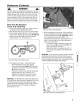
3. Carefullystand the Rear EngineRider on its rear
bumper.
4. Depress the clutch/brake pedal (A, Figure39) all the
way down. Move and hold the park brakelever (B) in
the "ON" position and releasethe clutch/brake pedal to
set the park brake.
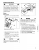
Figure 40:Adjusting the brake cable
6. If the measurement is not 3/4", loosen the two jam-nuts
(A, Figure 41). Hold the clutch/brake cable (B) to the
chain case bracket.
7. Adjust the cable up or down using the jam-nuts to
obtain a distance of 3/4" betweenthe end of the
clutch/brake cable (adjustment shown in inset of Figure
40) and the bottom of the housing.
8. After adjustment is complete, securely tighten the cable
jam-nuts.
9. Retestthe wheel brake.
Figure 39: Setting the park brake
5. Measurethe distance (A, Figure40) betweenthe end of
the clutch/brake cable (B) and the bottom of the housing
(C). The measurementshould be 3/4".
NOTE:The cotter pin, brake spring, and clutch yoke (D, E,
and F, Figure40) are noted for referencepurposes only.
Figure 41: Brakecable adjusting nuts
22 www.snapper.com