
Install Drawing


2
A
B
B
C
E
D
Figure 3
Figure 4
A
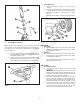
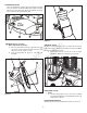
2. Steering Wheel Installation
NOTE: For more space between the seat and steering wheel, the
steering wheel can be rotated 180 degrees from the typical posi-
tion. The logo in the center of the steering wheel can be snapped
out and rotated also.
A. Slide the steering wheel (A, Figure 3) onto the steering
shaft. Normally, the offset of the steering wheel should
be towards operator’s seat.
B. Align the holes in the steering wheel and steering shaft.
Support the steering wheel and drive the 1/4” x 1-1/2”
roll pin (B) into the steering wheel and steering shaft.
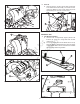
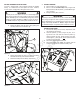
3. Installing Tie Rods
A. Install the bushings (C, Figures 1 & 4) onto the tie
rods (B).
B. Install the tie rods between the steering shaft (A, Figure
1) and steering arms (A, Figure 4). Secure with two 3/8”
flat washers (D, Figures 1 & 4) and 5/32” x 1” cotter-
pins (E).
NOTE: On some models, the tie rods come assembled.
LUBRICATION
1. Differential
A. Perform normal lubrication of the Rear Engine Rider.
Check the differential for proper lubricant levels. (Refer
to the Operator’s Manual.)
2. Chain Case
A. Perform normal lubrication of the Rear Engine Rider.
Check the chain case for proper lubricant levels. (Refer
to the Operator’s Manual.)
After completing lubrication, carefully lower the unit to
the floor to continue set-up.
FUEL SYSTEM
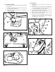
1. Fuel Tank Installation
A. Insert the fuel tank (A, Figure 5) into the fuel tank
bracket (B).
IMPORTANT:
Carefully guide the fuel barb on the
bottom of the fuel tank (C, inset) through the hole in the
bracket (D). Improper installation may result in damage
to the fuel barb and possible fuel leakage.
B. Install the canister/holder assembly (A, Figure 6) over
the fuel tank. Press down on the canister/holder assem-
bly while securing the bottom of the assembly to the
tank bracket with two torx screws (B). Tighten securely.
C. Install the hose clamp (B, Figure 7) approx. 1” onto the
end of the vent hose (A). Connect the vent hose to the
vent on the top front section of the fuel tank (C), then
move the hose clamp toward the end of the hose.
Figure 2
F
C
E
D
A
B
Not for
Reproduction