Ask-a-Tech Operations Launching Ask-a-Tech 9.2 Launching Ask-a-Tech Tap the Ask-a-Tech button on the Home screen to launch the website. Ask-a-Tech information is vehicle specific and a vehicle must be identified before the Home Page opens. Expect one of the two following results when Ask-a-Tech is selected: 1. A confirmation message displays if the diagnostic platform recognizes an active vehicle: a. Select OK to continue with the identified vehicle. b. Select Cancel to identify a different vehicle.
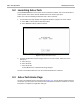
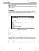
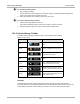
Ask-a-Tech Operations Ask-a-Tech Home Page Figure 9-2 Sample Ask-a-Tech page There are two main sections on the home page: • Ask-a-Tech Pulse • What Do You Want To Do? 9.3.1 Ask-a-Tech Pulse The Ask-a-Tech Pulse is a capsule summary of recent activity. Selecting an item from the list opens the complete tip. An icon along the right-hand edge indicates the type of tip: Icon Description Name Question Indicates a question a member is asking of the group.
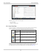
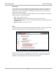
Ask-a-Tech Operations Ask-a-Tech Home Page Figure 9-3 Sample Ask-a-Tech tip page Hover over an acronym with a dashed underline in a Tip and a popup with the acronym definition opens as shown in the illustration above. Tip pages may also include hyperlinks that take you to test procedures and Fast-Track Troubleshooter references. 9.3.
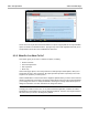
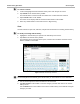
Ask-a-Tech Operations Ask-a-Tech Home Page Perform a Search Enter an item in the search field near the top of the page and click Search, or enter a keyboard return, to initiate the search. The screen updates to show the search results (Figure 9-4). Figure 9-4 Sample Ask-a-Tech search results Use the scroll bar at the right of the results to view the entire page. Use the “Showing page” bar at the bottom of the page to navigate between pages.
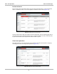
Ask-a-Tech Operations Ask-a-Tech Home Page Use the scroll bar to view the entire page and the “Showing page” bar at the bottom of the page to navigate between pages. Selecting a question from the list opens the discussion and gives you the opportunity to join in and share your expertise. Ask a Question Use this option to solicit advice from the group when you run into a situation that seems to defy logic.
Ask-a-Tech Operations Ask-a-Tech Home Page Enter a Tip Use this option to share your experiences with other members by creating a Tip. Posting a Tip requires the use of Microsoft Silverlight, a supplemental software program. The first time you select Enter a Tip you are prompted to install Silverlight. Follow the on-screen instructions to download and install the software. Refresh the screen after Silverlight is installed and the Enter a Tip form displays.
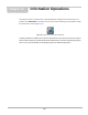
Chapter 10 Information Operations After using the Scanner, Component Test, and Scope Multimeter to diagnose and locate the source of a problem, select Information on the Home screen to link to resources that help you fix the problem and get the vehicle back in service (Figure 10-1). Figure 10-1 Sample Home screen Information button ShopKey5 software is available as an option for North America. An internet connection is required.
Chapter 11 Vehicle History Operations The Vehicle History refers to any work in progress, such as a repair order, estimate or invoice, that has customer, vehicle, and repair information for a vehicle in your shop. The Vehicle History is the starting point for using the Diagnostic Platform. The Scanner and Component Test software get vehicle information from the Vehicle History, and can only start after a Vehicle History is opened. 11.
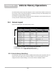
Vehicle History Operations z Screen Layout To sort Vehicle History items: 1. Tap a category heading. The listed items resort according to the selected category. A triangle appears alongside the name of the column that was used for the sort. 2. Select the triangle in the heading to reverse the sort order. z To resize a Vehicle History column: 1. Touch the line separating two columns. A line with arrowheads appears to show the column is ready for resizing. 2.
Vehicle History Operations z Screen Layout To activate a vehicle: 1. Locate and highlight the desired Vehicle History in the main body of the screen. 2. Tap Activate on the Vehicle History toolbar. The Activate button in removed from the toolbar once a vehicle has been selected. 3. Tap the Home button on the Toolbar. The Home screen displays with the activated vehicle shown on the toolbar. 4. Select any module button on the Home screen to begin testing.
Vehicle History Operations Screen Layout Delete Use the Delete button to remove unwanted items from the Vehicle History list. Simply highlight the item to remove, then select Delete. Search and Show All Selecting Search opens a dialog box that allows you to search Vehicle History items by category (Figure 11-3). Figure 11-3 Sample Search dialog box z To search: 1. Tap Search on the Vehicle History toolbar to open the search window. 2.
Vehicle History Operations Screen Layout Settings Use Settings to determine which categories of information display in the main body of the Vehicle History screen. Selecting the Settings button opens a dialog box. z To change Settings: 1. Tap Settings on the Vehicle History toolbar to open the dialog box. Figure 11-4 Sample Settings dialog box. 2.
Chapter 12 Data Manager Operations The Data Manager module is used to store, sort, and review saved files. Most operations are controlled through the toolbar. 12.1 Screen Layout Select Data Manager on the Module toolbar to open the file system. Use the toolbar at the top of the screen to navigate through the data. The folders panel below the toolbar displays the contents of the Windows “My Documents” folder, which is the Data Manager main screen.
Data Manager Operations Navigation 12.2 Navigation Use the toolbar buttons as shown in the table below to navigate through the Data Manager: Table 12-1 Data Manager toolbar buttons Name Description Button My Data Returns to the Data Manager main screen. Up Moves the items displayed in the folders panel up one level in the file structure. Open Opens the highlighted folder or file. New Creates a new folder. Delete Moves the highlighted file or folder to the recycling bin.
Data Manager Operations Operations 12.3.2 Up This button moves the items shown in the folders panel of the screen up in the file structure one level at a time. For example; one tap of the Up button when viewing the contents of the Scanner Data Folder returns you to the main screen. A second tap would display the contents of the “My Documents” folder. 12.3.3 Open The Open button is only active (displays in color) when an item in the folders panel is highlighted. z To open a folder: 1.
Data Manager Operations z Operations To create a new folder: 1. Tap the New button on the toolbar. The New Folder Name dialog box opens (Figure 12-3). 2. Touch the entry field on the dialog box to open the virtual keyboard. 3. Type a name for the new folder using the virtual keyboard. 4. Tap the OK button to create the new folder and return to the previous page. The Cancel button returns you to the previous page without creating a new folder. Figure 12-3 Sample New Folder name dialog box 12.3.
Data Manager Operations Operations Figure 12-4 Sample delete confirmation message 3. Tap Yes to delete the selected item and return to the previous page. The No button returns you to the previous page without deleting the selected item. 12.3.6 Rename The Rename button allows you to change the name of a folder or items within a folder. z To rename an item: 1. Highlight the item or folder to be renamed. 2. Tap the Rename button on the toolbar. The New Name dialog box opens (Figure 12-3).
Data Manager Operations Operations 3. Touch the entry field on the dialog box to open the virtual keyboard. 4. Type the new name into the entry field using the virtual keyboard. 5. Tap the OK button to change the name and return to the previous page. The Cancel button returns you to the previous page without changing the name. 12.3.7 Save The Save button is not implemented at this time. 12.3.
Data Manager Operations Saved File Structure 12.3.9 More Selecting the More button opens a dropdown menu with two options: • Shortcut—creates a shortcut to the highlighted item on the Data Manager main screen. A confirmation message displays when this option is selected. • Email—opens a new e-mail message with the selected file attached. The display device must have an active e-mail account to use this feature. 12.
Help Operations Chapter 13 Selecting Help from the Home screen opens this manual in a dedicated screen viewer. Navigate through the file either by gesture scrolling on the touch screen, or with the scroll bar along the right edge of the viewing screen. A left-to-right scroll bar appears at the bottom of the screen when magnification is increased. All listings in the Contents and Index are active links. Tap an entry with the stylus to go directly to that point of the document.
Chapter 14 System Settings Operations Selecting System Settings from the Home screen opens a menu with two options: • Paired Devices • Shop Information Paired Devices allows you to check the status of and to pair wireless devices, such as the Scan Module, to the Display Device. Shop Information allows you to create and edit a personalized header that is included on printed documents. 14.
System Settings Operations Paired Devices The Hardware Status indicators in the lower-right corner of the Home screen provides a quick reference of which modules have been paired to the Display Device (Table 14-1): Table 14-1 Hardware Status indicators Not Paired Module Paired Scanner Scope Multimeter 14.1.1 Pairing the Scan Module The Scan Module needs to be either connected to a vehicle or connected to a powered USB port so that it is powered up during the pairing procedure.
System Settings Operations Shop Information 8. Tap to select the Scan Module from the search results list. A search in progress message displays during the pairing procedure (Figure 14-3), the Paired Devices screen (Figure 14-1) displays once the procedure completes. Figure 14-3 Sample pairing in progress message 9. Tap the Home button on the Toolbar to return to the Home screen. 10. Disconnect the data cable from the vehicle.
System Settings Operations Shop Information Figure 14-4 Sample Shop Information dialog box 3. Tap within any of the information fields and the virtual keyboard opens. 4. Use the virtual keyboard to fill in the Shop Information form. As an alternative, you can connect a USB keyboard to a USB port on the Display Device and use it to enter information into the form. i NOTE: The screen does not scroll.
Chapter 15 Maintenance This section covers how to care for your Diagnostic Platform components. 15.1 Display Device Perform the following services on your Display Device on a routine basis to keep it in top condition. 15.1.1 Cleaning the Touch Screen The touch screen can be cleaned with a soft cloth and alcohol or a mild window cleaner. IMPORTANT: Do not use any abrasive cleansers or automotive chemicals on the touch screen. 15.1.
Maintenance Display Device Figure 15-2 Selecting a calibration option – Standard—uses 5 points on the screen to quickly bring the unit into calibration. Use the stylus to calibrate the screen. – Advanced—uses 9, 16, or 25 points on the screen to accurately bring the unit into calibration. Use the dropdown menu to select the number of points, a stylus is required to calibrate the screen. 4. Touch and hold the center of each red box that displays in sequence. Figure 15-3 Sample calibration target 5.
Maintenance z Display Device To calibrate the touch screen without the unit installed in docking cradle: 1. From the Windows toolbar select Start > Control Panel > Display. The Display Properties dialog box opens. 2. From the dialog box select Settings > Advanced. The Default Monitor and Intel Driver dialog box opens. 3. From the dialog box select the Display Config tab. 4. From the Display Config tab, select LVDS (clone) CRT from the Display Configuration dropdown menu (Figure 15-4).
Maintenance Display Device 4. With the Multiple Monitor Support box checked, select the Map Touch Screens button (Figure 15-5). Figure 15-5 Sample Multiple Monitors tab 5. Follow the screen prompts and touch the screen of the D7 Display Device as requested. 6. Type “S” on the USB keyboard to skip for extended display as requested. 7. Select OK from the Multiple Monitors tab to close the PenMount Control Panel dialog box. 8. Calibrate the touch screen using the standard procedure. 15.1.
Maintenance Display Device :$51 ,1* Risk of explosion. • The Lithium battery is factory replaceable only, incorrect replacement or tampering with the battery pack may cause an explosion. Explosion can cause death or serious injury. Battery Safety Guidelines IMPORTANT: The battery pack contains no user serviceable components. Tampering with the battery pack terminals or housing will void the product warranty.
Maintenance z Display Device To replace the battery pack: 1. Loosen the two captive screws the secure the battery pack to the back of the unit. 2. Insert a fingernail into the recess at the mid point of the top of the battery pack, then gently raise the battery pack up to release the electrical connector. 1— Captive Screws 2— Lifting Recess Figure 15-6 Display Device battery pack replacement 3. Lift the battery pack clear of the unit. 4.
Maintenance Display Device Figure 15-7 sample WEEE logo i NOTE: Always dispose of materials according to local regulations. Contact your sales representative for details. Battery Pack Calibration The internal battery pack contains a micro controller that monitors the battery pack characteristics and maintains an internal “fuel gauge”. The internal fuel gauge may lose some accuracy after many cycles of partial discharge and charge.
Maintenance Scan Module A progress indicator displays while the files are being restored. 4. Select OK from the confirmation message. The Display Device shuts down, then reboots and the system recovery portion of the operation begins. Follow any on-screen prompts. The Display Device shuts down and reboots a second time. When the Home screen displays, the procedure is complete and the Display Device is ready for use. 15.2 Scan Module This section covers how to care for your Scan Module. 15.2.
Software License Agreement, North America SNAP-ON INCORPORATED LICENSE AGREEMENT YOU SHOULD CAREFULLY READ THE FOLLOWING TERMS AND CONDITIONS BEFORE INSTALLING THIS SOFTWARE PACKAGE. WHOEVER INSTALLS THIS SOFTWARE PACKAGE MUST EITHER BE THE PERSON WHO ACQUIRED THE SOFTWARE OR A PERSON AUTHORIZED BY THE PERSON OR ENTITY WHO ACQUIRED THE SOFTWARE TO ACCEPT THE FOLLOWING TERMS ON SUCH PERSON'S OR ENTITY'S BEHALF. “YOU” AND “YOUR” SHALL REFER TO THE PERSON OR ENTITY WHO ACQUIRED THIS PRODUCT.
Software License Agreement, North America SNAP-ON INCORPORATED LICENSE AGREEMENT WARRANTIES (IF ANY), ALL OF WHICH ARE DISCLAIMED BELOW. THIS LIMITED WARRANTY IS THE ONLY EXPRESS WARRANTY THAT IS PROVIDED TO YOU AND IS NOT TRANSFERABLE OR ASSIGNABLE.
Software License Agreement, North America SNAP-ON INCORPORATED LICENSE AGREEMENT RESTRICTED RIGHTS The Software is provided with RESTRICTED RIGHTS. Use, duplication, or disclosure by or on behalf of any unit or agency of the United States Government (the “Government”) is subject to restrictions as set forth in subparagraph (c)(1) of the Rights in Technical Data and Computer Licensed Software clause at DFARS 252.
Software License Agreement, North America EXHIBIT A: SNAP-ON INCORPORATED PRIVACY POLICY EXHIBIT A: SNAP-ON INCORPORATED PRIVACY POLICY The privacy of your personally identifiable information is important to us.
Software License Agreement, North America EXHIBIT A: SNAP-ON INCORPORATED PRIVACY POLICY We may share Personal Information with our consultants or service providers to help us serve you better. We also contract other companies and individuals (collectively “Suppliers”) to perform functions on our behalf, including without limitation, fulfilling and processing orders, handling shipping and returns, sending communications to you, and providing customer services.
Index A AC/DC power supply 6 actuator tests 31 Alarms 43 alligator clips 73 B battery pack 6 calibrating 124 disposal 123 handling 122 replacing 122 specifications 5 battery recycling 123 battery service 121 C cables 72–74 channel 1 72 channel 2 72 channel 3 73 channel 4 73 inductive RPM pickup 74 secondary coil adapter 74 secondary ignition clip-on wire adapter 74 camera 20 capabilities, hardware 71 Clear Codes 31 clear codes 54 clearing codes 37 Codes Menu 31 codes.
Index M M Main Body 76 Making Selections 79 Scanner 30 manual conventions description 1 notes 2 Memory Resets 31 menu button 13 Messages confirmation 30 error 30 warning 30 messages safety iii–iv meter capabilities 71 Modules 11 O OBD Diagnose 55–59 OBD Health Check 52–54 operating temperature 6, 8, 10 Operations Component Tests 65 operations connecting to a vehicle 26, 31 identifying a test vehicle 31 selecting a system to test 31 selecting tests 31 oxygen sensor tests 41 P parameters.
Index T software Troubleshooter 41 speed units 15 stand, the 19 storage temperature 6, 8, 10 subsystem tests 39 Sweep 48 System Settings 114–116 system tests 31, 39 W weight, unit 5, 8, 10 wireless pairing devices 114–116 wireless communication 7 T temperature operating 6, 8, 10 storage 6, 8, 10 temperature units 15 test leads 72–74 test probes 73 tests actuator 31 component 39 functional 31, 39 selecting 31 subsystem 39 system 31, 39 toggle tests 39 Toolbar 13–116 Vehicle History 102 toolbar record/pla
Federal Communication Commission Interference Statement 15.105 Class B digital device This equipment has been tested and found to comply with the limits for a Class B digital device, pursuant to part 15 of the FCC rules. These limits are designed to provide reasonable protection against harmful interference in a residential installation.
4RF Exposure Information (SAR) This device is designed and manufactured not to exceed the emission limits for exposure to radio frequency (RF) energy set by the Federal Communications Commission of the United States, Industry Canada of Canada. During SAR testing, this device was set to transmit at its highest certified power level in all tested frequency bands, and placed in positions that simulate RF exposure in usage against the head with no separation, and near the body.