
User's Manual
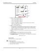
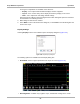
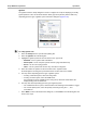
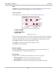
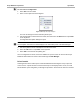
Table Of Contents
- 17 MARS-3102 User Manual_0904
- 17 MARS-3102 User Manual_0731
- Safety Information
- Contents
- Using This Manual
- Introduction
- Getting Started
- Navigation
- Scanner Operations
- OBD Direct Operations
- Component Test Operations
- Scope Multimeter Operations
- Ask-a-Tech Operations
- Information Operations
- Vehicle History Operations
- Data Manager Operations
- Help Operations
- System Settings Operations
- Maintenance
- Software License Agreement, North America
- Index
- 文件2
- 17 MARS-3102 User Manual_0731
- RF Exposure Information (SAR) CCS

84
Scope Multimeter Operations Operations
1— Source—selects the triggering event:
- Trace 1—sets the trigger to channel 1.
- Trace 2—sets the trigger to channel 2.
- Trace 3—sets the trigger to channel 3.
- Trace 4—sets the trigger to channel 4.
- Cylinder—sets triggering to the firing of a cylinder detected by the optional RPM
Pickup or Secondary Ignition Adapter.
- None—switches triggering off.
2— Mode—sets the method of triggering:
- Auto (automatic)—if a trigger is found, the waveform displays. If a trigger is not found
after about a half second, the waveform and a “trigger not found” message displays.
- Manual—if a trigger is found, the waveform displays. If a trigger is not found nothing
displays (no waveform and no message).
3— Slope—sets triggering to the rising (top button) or falling (lower button) slope of the signal
waveform.
4— Vertical position—moves the trigger position up and down on the grid.
5— Horizontal position—moves the trigger timing left and right on the grid
6— Select Back to return to the Preferences dialog box, or select Exit to close the dialog box
and return to the scope.
Figure 8-19 Trigger controls
View Controls
Use the view controls to set display attributes.
z To adjust view controls:
1. Select Setup from the Scope Multimeter toolbar.
The Scope Multimeter Preferences dialog box opens.
2. Select View to open a submenu.