
User's Manual
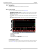
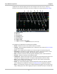
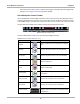
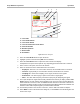
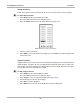
Table Of Contents
- 17 MARS-3102 User Manual_0904
- 17 MARS-3102 User Manual_0731
- Safety Information
- Contents
- Using This Manual
- Introduction
- Getting Started
- Navigation
- Scanner Operations
- OBD Direct Operations
- Component Test Operations
- Scope Multimeter Operations
- Ask-a-Tech Operations
- Information Operations
- Vehicle History Operations
- Data Manager Operations
- Help Operations
- System Settings Operations
- Maintenance
- Software License Agreement, North America
- Index
- 文件2
- 17 MARS-3102 User Manual_0731
- RF Exposure Information (SAR) CCS

75
Scope Multimeter Operations Navigation
8.3 Navigation
The following section describes how to navigate the screen interface.
8.3.1 Screen Layout
The screens typically include the following sections (
Figure 8-14):
• Scope Multimeter Toolbar—allows you to configure the tool for the type of test and to adjust
the settings for each channel, or trace.
• Main Body of the screen—displays test results. Options on the toolbar let you select how
tests display on the screen.
• Trace Details—displays trace settings, which can be adjusted or switched through the touch
screen
• Record/Playback Control Toolbar—allows you to record and navigate through paused data.
1— Scope Multimeter toolbar
2— Main body
3— Trace Details
4— Record/Playback Control toolbar
Figure 8-14 Scope Multimeter screen layout
Scope Multimeter Toolbar
The Scope Multimeter toolbar is used to set up the tool for testing and to configure the settings for
each trace.
Table 8-4 on page 76 gives brief descriptions of the control buttons on the toolbar: