
User's Manual
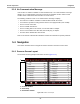
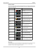
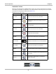
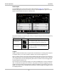
Table Of Contents
- 17 MARS-3102 User Manual_0904
- 17 MARS-3102 User Manual_0731
- Safety Information
- Contents
- Using This Manual
- Introduction
- Getting Started
- Navigation
- Scanner Operations
- OBD Direct Operations
- Component Test Operations
- Scope Multimeter Operations
- Ask-a-Tech Operations
- Information Operations
- Vehicle History Operations
- Data Manager Operations
- Help Operations
- System Settings Operations
- Maintenance
- Software License Agreement, North America
- Index
- 文件2
- 17 MARS-3102 User Manual_0731
- RF Exposure Information (SAR) CCS

27
Scanner Operations Navigation
5.3.2 No Communication Message
If the Scanner is unable to establish a communications link, a “no communications” message
displays. A “no communication” message, means the Scan Module and the vehicle control
module cannot communicate with each other for some reason.
The following conditions cause a “no communication” message to display:
• The Scanner is unable to establish a communication link with the vehicle.
• You selected a system for testing that the vehicle is not equipped with (such as ABS).
• There is a loose connection.
• There is a blown vehicle fuse.
• There is a wiring fault on the vehicle, or in the data cable or adapter.
• There is a circuit fault in the data cable, Personality Key, or adapter.
• Incorrect vehicle identification was entered.
Refer to the Vehicle Communication Software manuals for manufacturer-specific problems.
5.4 Navigation
This section describes how to navigate the Scanner interface and select scanner tests.
5.4.1 Scanner Screen Layout
The Scanner screens typically include three sections (
Figure 5-10):
1— Scanner Toolbar
2— Main Body
3— Data Buffer Toolbar
Figure 5-10 Scanner screen layout