
User's Manual
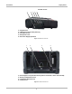
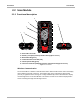
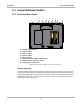
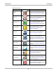
Table Of Contents
- 17 MARS-3102 User Manual_0904
- 17 MARS-3102 User Manual_0731
- Safety Information
- Contents
- Using This Manual
- Introduction
- Getting Started
- Navigation
- Scanner Operations
- OBD Direct Operations
- Component Test Operations
- Scope Multimeter Operations
- Ask-a-Tech Operations
- Information Operations
- Vehicle History Operations
- Data Manager Operations
- Help Operations
- System Settings Operations
- Maintenance
- Software License Agreement, North America
- Index
- 文件2
- 17 MARS-3102 User Manual_0731
- RF Exposure Information (SAR) CCS

9
Introduction Scope Multimeter Module
2.3 Scope Multimeter Module
2.3.1 Functional Description
1— Common (Ground) Port
2— Channel 1 Port
3— Channel 2 Port
4— Channel 3 Port
5— Channel 4 Port
6— Auxiliary Port (not visible in illustration)
7— USB Port (under protective cover)
8— Display Device Connection
Figure 2-5 Scope Multimeter Module, removed from Display Device
Remote Operation
The Scope Multimeter Module installs into the Display Device and is held in place by a lock tab.
Depress the lock tab and the Scope Multimeter Module is easily removed from the Display Device.
A USB cable (supplied with your kit) can then be used to connect the Scope Multimeter Module to
the Display Device. Now, you can continue to remotely monitor circuit activity while moving the
Display Device around the vehicle.
:$51,1*
&$87,21
5,6.2)(;3/26,21
)/$0$%/()8(/$1'9$3256&$1,*1,7(
7+,6(48,30(17+$6,17(51$/$5&+,1*2563$5.,1*3$576
'2127(;326(72)/$00$%/(9$3256
/2&$7(7+,6(48,30(17$7/($67PP,1&+(6
$%29(7+()/225
5,6.2)(/(&75,&$/6+2&.
'21275(029(&29(525%$&.
1286(56(59,&$%/(3$576,16,'(
5()(56(59,&,1*7248$/,),('6(59,&(3(56211(/
(;3/26,2125)/$0(&$1&$86(,1-85<
(/(&75,&$/6+2&.&$1&$86(,1-85<