
User's Manual

55
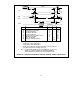
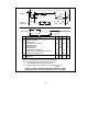
nPULSE1
t2
* t2,t7,t10 = 4 x (crystal period) for clock frequencies other than 20 MHz.
t3
* t3,t11 = 8 x (crystal period) for clock frequencies other than 20 MHz.
This period applies to data of two consecutive one's.
RXIN
t10
t11
nPULSE2
t5 t6
(Internal Clk)
t4
* t5,t6 = 2 x (crystal period) for clock frequencies other than 20 MHz.
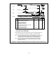
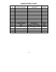
Parameter min typ max units
t2
t3
t4
t5
t6
t7
t8
t10
t11
nPULSE1 Pulse Width
nPULSE1 Period
nPULSE2 Low to nPULSE1 Low
nPULSE2 High Time
nPULSE2 Low Time
nPULSE2 Period
nPULSE2 High to nTXEN High
RXIN Pulse Width
RXIN Period
nS
nS
nS
nS
nS
nS
nS
nS
nS
200*
400*
100*
100*
200*
200*
400*
25
50
-25
0
10
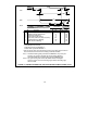
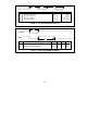
t1
t7
nTXEN
t9
t8
LAST BIT
(400 nS BIT TIME)
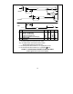
t1
nPULSE2 High to nTXEN Low
0 50
nS
(First rising edge on nPULSE2 after Last Bit Time)
t9
nTXEN Low to first nPULSE1 Low**
650 750
nS
** t9: For clock frequencies other than 20 MHz, t9 = 14 x (clock period) + 50 nsec.
FIGURE 15 - BACKPLANE MODE TRANSMIT OR RECEIVE TIMING
(These signals are to and from the differential driver or the cable)