
User's Manual
23
Transmitter is disabled, the Receiver portion of
the device is still functional and will provide the
user with useful information about the network.
The Node ID Register defaults to the value 0000
0000 upon hardware reset only.
Next ID Register
The Next ID Register is an 8-bit, read-only
register, accessed when the sub-address bits
are set up accordingly (please refer to the
Configuration Register). The Next ID Register
holds the value of the Node ID to which the
COM20020 will pass the token. When used in
conjunction with the Tentative ID Register, the
Next ID Register can provide a complete
network map. The Next ID Register is updated
each time a node enters/leaves the network or
when a network reconfiguration occurs. Each
time the microsequencer updates the Next ID
Register, a New Next ID interrupt is generated.
This bit is cleared by reading the Next ID
Register. Default value is 0000 0000 upon
hardware or software reset.
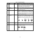
Status Register
The COM20020 Status Register is an 8-bit read-
only register. All of the bits, except for bits 5
and 6, are software compatible with previous
SMSC ARCNET devices. In previous SMSC
ARCNET devices the Extended Timeout status
was provided in bits 5 and 6 of the Status
Register. In the COM20020, the COM90C66,
and the COM90C165, COM20020-5,
COM20051 and COM20051+ these bits exist in
and are controlled by the Configuration Register.
The Status Register contents are defined as in
Table 4, but are defined differently during the
Command Chaining operation. Please refer to
the Command Chaining section for the definition
of the Status Register during Command
Chaining operation. The Status Register
defaults to the value 1XX1 0001 upon either
hardware or software reset.
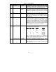
Diagnostic Status Register
The Diagnostic Status Register contains seven
read-only bits which help the user troubleshoot
the network or node operation. Various
combinations of these bits and the TXEN bit of
the Configuration Register represent different
situations. All of these bits, except the
Excessive NAcK bit and the New Next ID bit, are
reset to logic "0" upon reading the Diagnostic
Status Register or upon software or hardware
reset. The EXCNAK bit is reset by the "POR
Clear Flags" command or upon software or
hardware reset. The Diagnostic Status Register
defaults to the value 0000 000X upon either
hardware or software reset.
Command Register
Execution of commands are initiated by
performing microcontroller writes to this
register. Any combinations of written data
other than those listed in Table 6 are not
permitted and may result in incorrect chip
and/or network operation.
Address Pointer Registers
These read/write registers are each 8-bits wide
and are used for addressing the internal RAM.
New pointer addresses should be written by first
writing to the High Register and then writing to
the Low Register because writing to the Low
Register loads the address. The contents of the
Address Pointer High and Low Registers are
undefined upon hardware reset. Writing to
Address Pointer low loads the address.