
User's Manual

CONFIDENTIAL AND PROPRIETARY
The Information contained in this document shall remain the sole exclusive property of s.m.s, smart microwave sensors GmbH and shall not
be disclosed by the recipient to third parties without prior consent of s.m.s, smart microwave sensors GmbH in writing.
UMRR-96 Type 153 User Manual.docx Version 2 I Page 10 of 15 I January 23, 2020
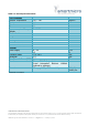
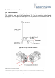
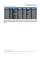
Table 6-1: Sensor connector pin-out
TE
1411001-1
Pair
Label
DSUB-9-
w CAN1
DSUB-9-
w CAN2
Banana
plug
TE
1355348-1
1
1
GND
3
3
Black
2
2
BroadR_P
9
3
3
CAN2_H
7
4
3
CAN2_L
2
5
1
V+
Red
6
2
BroadR_N
8
7
4
CAN1_H
7
8
4
CAN1_L
2
-
SHIELD
3
Please note that in the standard configuration the sensor has 120 Ohms resistor on board
(CAN bus termination between CAN_L and CAN_H). A number of cable sets for initial
operation and test purposes are offered by Smartmicro, to deliver a fast set-up of a sensor
system.