Project Documentation | UMRR-96 Type 153 User Manual Project Number: ... SMS Project Number: Project Title: UMRR-96 Type 153 User Manual Keyword(s): UMRR-96 Type 153 radar sensor Date: January 23, 2020 Document: UMRR-96 Type 153 User Manual.docx Version: 2 CONFIDENTIAL AND PROPRIETARY The Information contained in this document shall remain the sole exclusive property of s.m.s, smart microwave sensors GmbH and shall not be disclosed by the recipient to third parties without prior consent of s.m.
1 Contents 1 2 3 4 5 6 7 8 9 Contents .................................................................................................................... 2 Abbreviations ............................................................................................................. 3 Introduction ............................................................................................................... 4 General description ................................................................................
2 Abbreviations ADC Analog-to-digital converter CAN Controller area network DSP Digital signal processing; digital signal processor FMCW Frequency modulated continuous wave MMIC Monolithic microwave integrated circuit UMRR Universal medium-range radar CONFIDENTIAL AND PROPRIETARY The Information contained in this document shall remain the sole exclusive property of s.m.s, smart microwave sensors GmbH and shall not be disclosed by the recipient to third parties without prior consent of s.m.
3 Introduction This document is a short documentation of the general purpose universal medium range radar (UMRR) UMRR-96 Type 153 radar sensor with type 153 antenna. CONFIDENTIAL AND PROPRIETARY The Information contained in this document shall remain the sole exclusive property of s.m.s, smart microwave sensors GmbH and shall not be disclosed by the recipient to third parties without prior consent of s.m.s, smart microwave sensors GmbH in writing. UMRR-96 Type 153 User Manual.
4 General description 4.1 Sensor description The main task of the UMRR is the detection of any reflectors in the field of view, to measure the distance, the relative speed and the angle to the shortest reflector (and to other reflectors), to detect motion and to track (filter) the results over time.
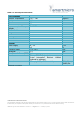
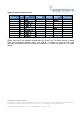
Table 4-1: General performance data Environmental Ambient Temperature Shock Vibration IP Pressure / Transport Altitude Mechanical Weight Dimensions Housing Identification Antenna Identification DSP Board Identification General Power Supply -40 ... +85 100 14 67 0…10.000 degree C grms grms ≤153 See 5.2 0B 99 96 g m 8 ... 24 I V DC <5 W Frequency Band 77.0…81.0 GHz Bandwidth <4 GHz Max. Transmit Power (EIRP) 31.0 dBm Interfaces Primary CAN V2.
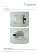
5 Hardware 5.1 UMRR sensor An example picture of a UMRR-96 Type 153 sensor is shown in the figures below, see Figure 5-1 and Figure 5-2. Figure 5-1: Front view of UMRR-96 Type 153 Figure 5-2: Rear View of UMRR-96 Type 153 CONFIDENTIAL AND PROPRIETARY The Information contained in this document shall remain the sole exclusive property of s.m.s, smart microwave sensors GmbH and shall not be disclosed by the recipient to third parties without prior consent of s.m.s, smart microwave sensors GmbH in writing.
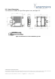
5.2 Sensor Dimensions The dimensions of UMRR-96 Type 153 are given in mm, see Figure 5-3. Figure 5-3: Dimensions of sensor UMRR-96 Type 153 CONFIDENTIAL AND PROPRIETARY The Information contained in this document shall remain the sole exclusive property of s.m.s, smart microwave sensors GmbH and shall not be disclosed by the recipient to third parties without prior consent of s.m.s, smart microwave sensors GmbH in writing. UMRR-96 Type 153 User Manual.
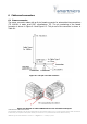
6 Cables and connectors 6.1 Sensor connector The sensor connector mates with an 8-pin female connector for automotive interconnections (TE 1411001-1: water proof IP67, manufacturer TE). The pin numbering of the female connector is shown in Figure 6-1 and Figure 6-2. The pin-out of the connector is shown in Table 6-1.
Table 6-1: Sensor connector pin-out TE 1411001-1 1 2 3 4 5 6 7 8 Pair Label 1 2 3 3 1 2 4 4 - GND BroadR_P CAN2_H CAN2_L V+ BroadR_N CAN1_H CAN1_L SHIELD DSUB-9w CAN1 3 DSUB-9- Banana w CAN2 plug 3 Black TE 1355348-1 9 7 2 Red 8 7 2 3 Please note that in the standard configuration the sensor has 120 Ohms resistor on board (CAN bus termination between CAN_L and CAN_H).
7 Data interfaces 7.1 CAN data interface This specification gives a detailed description of the CAN data communication used in the UMRR based systems on the sensor CAN. The UMRR is compliant with CAN 2.0B standard. CAN is a very robust full duplex bidirectional interface. 7.
Figure 7-1: CAN bit timing for UMRR sensor Figure 7-2: CAN bit timing as defined by the CAN protocol CONFIDENTIAL AND PROPRIETARY The Information contained in this document shall remain the sole exclusive property of s.m.s, smart microwave sensors GmbH and shall not be disclosed by the recipient to third parties without prior consent of s.m.s, smart microwave sensors GmbH in writing. UMRR-96 Type 153 User Manual.
8 Applications The sensor is very versatile and can be used for all kind of 360 degree short- and medium range applications. The sensor is especially well suited for all kind of blind spot detection (BSD) and lane change assist (LCA) applications. It can be applied for short- and medium range collision warning (CW) applications for autonomous driving. One or multiple sensors are specifically integrated into vehicle models of automotive OEMs.
9 Declaration of Conformity 9.1 Declaration of Conformity for USA This device has been tested and found to comply with the requirements set forth in 47 CFR Part 95, Subpart M for both fundamental emissions and unwanted emissions. These limits are designed to provide reasonable protection against any harmful interference when the device is operated in a commercial environment. Changes or modifications made to this equipment not expressly approved by s.m.
IC Radiation Exposure Statement: This equipment complies with IC RSS-102 radiation exposure limits set forth for an uncontrolled environment. This equipment should be installed and operated with the minimum distance 20cm between the radiator & your body. 9.2.2 Déclaration de conformité en francais Le présent appareil est conforme aux CNR d'Industrie Canada applicables aux appareils radio exempts de licence.