
User's Manual

CONFIDENTIAL AND PROPRIETARY
The Information contained in this document shall remain the sole exclusive property of s.m.s, smart microwave sensors GmbH and shall not
be disclosed by the recipient to third parties without prior consent of s.m.s, smart microwave sensors GmbH in writing.
UMRR-11 Type 132 User Manual_V2.docx Version 2 I Page 5 of 17 I January 10, 2019
4 General description
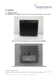
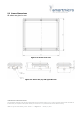
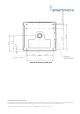
4.1 Sensor description
The main task of the UMRR is the detection of any reflectors in the field of view, to measure
the distance, the relative speed and the angle to the shortest reflector (and to other
reflectors), to detect motion and to track (filter) the results over time.
For this general purpose measurement application, range and relative radial speed and
the angle value of each reflector inside the antenna beam are measured and the results are
reported via the communication links cycle by cycle.
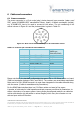
4.2 Transmit Signal
The UMRR transmit frequency is located in the 76 GHz to 77 GHz band, the used bandwidth
is smaller than 1 GHz. The maximum transmit power is smaller than 55dBm.
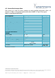
The UMRR-11 sensor type 132 provides 2 modes, AEB- and ACC-mode. Antenna type 132 is
used, consisting of three transmit and four receive antennas, both are linear polarized. The 2
way 3 dB cut-off angle by AEB-mode in azimuth is ± 25 deg. and in elevation is ± 4.1 deg.
The 2 way 3 dB cut-off angle by ACC-mode in azimuth is ± 7 deg. and in elevation is ± 4.1
deg.
The device uses different FMCW transmit signal waveforms for distance and speed
measurement.