
User's Manual

CONFIDENTIAL AND PROPRIETARY
The Information contained in this document shall remain the sole exclusive property of s.m.s, smart microwave sensors GmbH and shall not
be disclosed by the recipient to third parties without prior consent of s.m.s, smart microwave sensors GmbH in writing.
UMRR-11 Type 132 User Manual_V2.docx Version 2 I Page 14 of 17 I January 10, 2019
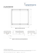
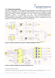
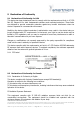
7.4 Transceiver schematics
In Figure 7-3 and Figure 7-4 the exact DSP board schematic of the UMRR is given. The CAN
pins of the Co-Processor are connected to a CAN transceiver, which is connected to the pins
CAN1_P and CAN1_N. Similarly, the RS485 pins of the Co-Processor are connected to a RS485
transceiver, which is connected to the pins RS485_TX_ETHRN_TX4_P,
RS485_TX_ETHRN_TX4_N, RS485_TX_CAN2_ETHRN_TX3_P, RS485_TX_CAN2_ETHRN_TX3_N.
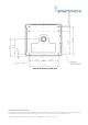
The Ethernet-Phy is connected to an Ethernet transformer, which is connected to the pins
ETHRN-TX1_P, ETHRN-TX1_N, ETHRN-TX2_P, ETHRN-TX2_N.
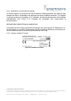
Figure 7-3: UMRR-11 DSP board schematics of CAN and RS485 transceivers
Figure 7-4: UMRR-11 DSP board schematics of Ethernet-Phy