
User's Manual

CONFIDENTIAL AND PROPRIETARY
The Information contained in this document shall remain the sole exclusive property of s.m.s, smart microwave sensors GmbH and shall not
be disclosed by the recipient to third parties without prior consent of s.m.s, smart microwave sensors GmbH in writing.
UMRR-11 Type 132 User Manual_V2.docx Version 2 I Page 13 of 17 I January 10, 2019
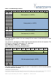
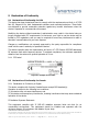
Table 7-1: RS-485 message structure
Byte\Bit
7
6
5
4
3
2
1
0
0
Start sequence (4 x UINT8)
0xCA
1
0xCB
2
0xCC
3
0xCD
x
Data payload (n x UINT8)
x
x
x
x
x
x
x
0
XOR Checksum (UINT8)
1
End sequence (4 x UINT8)
0xEA
2
0xEB
3
0xEC
4
0xED
Every data message consists of its own message ID, the number of used data bytes and the
data bytes itself.
The checksum is calculated on all data except the start sequence and the end sequence. The
Checksum is a simple XOR Assignment of all n data bytes.
Byte0 XOR Byte1 XOR Byte2 ... XOR Byte (n-1)
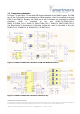
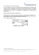
Table 7-2: Structure of a RS-485 data payload block
Byte\Bit
7
6
5
4
3
2
1
0
0
CAN message ID (UINT16)
High
1
Low
2
CAN message length (UINT8)
3
CAN data payload (length x UINT8)
4
5
6
7
8
9
10
The sensor receives only one message per cycle. It is important to wait for the end sequence
to send an additional command.