
User's Manual

CONFIDENTIAL AND PROPRIETARY
The Information contained in this document shall remain the sole exclusive property of s.m.s, smart microwave sensors GmbH and shall not
be disclosed by the recipient to third parties without prior consent of s.m.s, smart microwave sensors GmbH in writing.
UMRR-11 Type 132 User Manual_V2.docx Version 2 I Page 10 of 17 I January 10, 2019
6 Cables and connectors
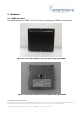
6.1 Sensor connector
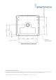
The sensor connector is a 12-pin male (plug) circular bayonet type connector (water proof
IP67, series LF10WBRB-12PD, manufacturer Hirose, Japan). A female counterpart (socket),
e.g. LF10WBP-12S, has to be used to connect to the sensor. The pin numbering of the
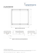
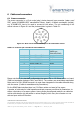
socket is shown in Figure 6-1 and the pin description is given in Table 6-1.
Figure 6-1: Rear view of female counterpart to be connected to sensor
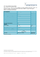
Table 6-1: Connector pin out model of sensor UMRR-11
Pin No.
Function
Wire Color
(MEDI type
#KU110C12J002)
1
Sensor Ethernet TX H
gray / red
2
Sensor Ethernet TX L
red / blue
3
Sensor RS485 RX L
pink
4
Sensor RS485 RX H
gray
5
Sensor RS485 TX L
brown
6
Sensor RS485 TX H
white
7
Sensor_GND
blue
8
Sensor_Vcc
red
9
Sensor Ethernet RX L
black
10
Sensor Ethernet RX H
purple
11
CAN H
green
12
CAN L
yellow
Please note that in the standard configuration the sensor has no 120 Ohms resistor on board
(CAN bus termination between CAN L and CAN H). The resistors are nevertheless required at
either end of a CAN / RS485 bus and is in most cases integrated in the cable delivered along
with the sensor (if cable is manufactured by Smartmicro).
For the RS485 data interface there is a 120 Ohms resistor on board of the sensor.
A number of cable sets for initial operation and test purposes are offered by Smartmicro, to
deliver a fast set-up of a sensor system. Among those preconfigured ready-to-run cables as
well as cable stumps (pig tail cables or various lengths) which carry the connector on one
side and open wires on the other.