
User's Manual

CONFIDENTIAL AND PROPRIETARY
The Information contained in this document shall remain the sole exclusive property of s.m.s smart microwave sensors GmbH and shall not
be disclosed by the recipient to third parties without prior consent of s.m.s smart microwave sensors GmbH in writing.
UMRR-0F0002-1D0907-050B00 General Purpose USA Version 1 I Page 7 of 23 I November 13, 2014
4.2 Transmit Signal
The UMRR transmit frequency is located in the 24 GHz ISM band (24075 MHz to 24175 MHz),
the used bandwidth is smaller than 100 MHz. The maximum transmit power is 24.0dBm.
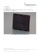
Antenna type 29 is used, consisting of one transmit and two receive antennas, both linear
polarized. The 2 way 3 dB cut-off angle in az. +-6deg. And in el. +-4deg.
The device uses different FMCW transmit signal waveforms for distance and speed
measurement.
4.3 General Performance Data
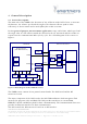
As soon as the device is powered up, the unit (TX and RX) starts operation. In Table 1:
General performance data general performance data are given.
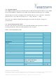
Table 1: General performance data
Environmental
Ambient Temperature
-40 ... +85
degree C
Shock
100
g
rms
Vibration
14
g
rms
IP
67
Pressure / Transport altitude
0…10.000
M
Mechanical
Weight
320
G
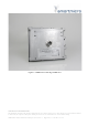
Dimensions
See 5.2
Housing Identification
050B00
Antenna Identification
1D0907
DSP Board Identification
0F0002
General
Power Supply
7 ... 40
3.7
V DC
W
Frequency Band
24.075…24.175
GHz
Bandwidth
< 100
MHz
Max. Transmit Power (EIRP)
24.0
dBm
Interfaces
CAN V2.0b (passive),
RS485 half or full duplex
100Base-T Ethernet
Connector
12 Pin plug Hirose LF10WBRB-
12PD
CAN, RS485,
Power, Eth.