
User's Manual

smart microwave sensors GmbH
CONFIDENTIAL AND PROPRIETARY
The Information contained in this document shall remain the sole exclusive property of s.m.s smart microwave sensors GmbH and shall not
be disclosed by the recipient to third parties without prior consent of s.m.s smart microwave sensors GmbH in writing.
2009-02-16 UMRR Documentation_v3 Page 8 of 18 February 16, 2009
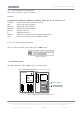
The UMRR consists of a DSP (digital signal processing) board controlling the RF circuit. All
interactions with the user are through the DSP board interfaces, mainly CAN (Controller Area
Network) interface.
The DSP board controls the VCO through an internal SPI (Serial Peripheral Interface). The
VCO signal is split into transmit and receive path. The transmit path feeds the TX antenna.
The receive path feeds mixers for the receive antennas.
The mixer outputs are fed into an A/D converter attached to the digital signal processor. All
Signal processing tasks there performed in this device.
Frequency band allocation is permanently controlled through a reference oscillator onboard
the RF circuit. The reference is controlled through internal SPI.
The UMRR unit hosts power supervisors and a watchdog. CAN bus has in built jabber inhibit.