
User's Manual


smart microwave sensors GmbH
CONFIDENTIAL AND PROPRIETARY
The Information contained in this document shall remain the sole exclusive property of s.m.s smart microwave sensors GmbH and shall not
be disclosed by the recipient to third parties without prior consent of s.m.s smart microwave sensors GmbH in writing.
2009-02-16 UMRR Documentation_v3 Page 9 of 18 February 16, 2009
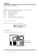
4 Sensor System Architectures
4.1 Stationary Applications
The UMRR sensor family can be used for many stationary applications. Among those are:
- Surveillance systems
- Moving objects detection
- Traffic monitoring
- Traffic enforcement
- Rail applications
etc.
In a stationary application, usually the sensor output is a list of detected targets (reflectors)
on the sensor CAN bus (referred to as
internal CAN
) with the parameters
- Range
- Angle (Position)
- Radial Speed
- Reflectivity level
- Type of Target (Reliability Figure).
In addition to that, status and diagnose data form the sensor are reported.
Usually the tracking (filtering and smoothing of all detected reflectors over time) is done in
an additional unit (central ECU BUMPER-08xx or a PC or the like). If required, those tracking
algorithms can also be integrated in the sensor.
The result of the tracking is an object list with the following parameters:
- x position
- y position
- x component of the velocity
- y component of the velocity
- type of reflector
- size of reflector.
When multiple sensors are applied, the data fusion algorithms are typically run on the fusion
PC or the fusion central ECU BUMPER08xx.
In any case, a visualization both of the targets and the objects is possible using the
DriveRecorder2 software in any PC equipped with a CAN card.