Annex No.
smart microwave sensors GmbH UMRR Universal Medium Range Radar Documentation CONFIDENTIAL AND PROPRIETARY The Information contained in this document shall remain the sole exclusive property of s.m.s smart microwave sensors GmbH and shall not be disclosed by the recipient to third parties without prior consent of s.m.s smart microwave sensors GmbH in writing.
smart microwave sensors GmbH Contents 1 Intended usage / application............................................................................3 2 Detection Performance Data .............................................................................4 2.1 FMCW Narrowband Mode ......................................................................................4 3 Radar System Components ...............................................................................6 3.1 Individual sensors .........
smart microwave sensors GmbH 1 Intended usage / application The UMRR-09xx (UMRR) device is used as a field disturbance sensor. The user installs the UMRR on a stationary or moving platform. As soon as power is applied to the UMRR, transmit and receive start operating. The UMRR sensor permanently monitors the volume within the vicinity of the antenna field pattern (compare section 5). The sensor itself is not rotated and has no moving parts. The sensor acts in measurement cycles of 30 .. 150ms.
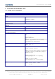
smart microwave sensors GmbH 2 Detection Performance Data 2.1 FMCW Narrowband Mode Parameter Value Basics: Frequency Band 24.000 GHz to 24.250 GHz Bandwidth < 100 MHz Transmit Peak Power (Individual Sensor) <= 20dBm Antenna: Antenna Type Type 29 Angle Interval (field of View) Type 29: +-20 degree Detection Performance: Range Interval Minimum Range: 0.
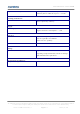
smart microwave sensors GmbH Separation of two objects Tracking Performance: Number of simultaneously tracked objects Supply: Power Supply Interface: CAN Bus To be separately detectable, two objects of identical reflectivity must be different in speed >= 0.25ms-1 Up to 32 (can be adjusted by software) 8…32V Single Sensor Power consumption: < 3,5W Interface V2.0B(passive) Data rate typically set to 500kbit/s (other data rates possible) Synchronous Serial IF Not accessible for customers.
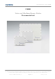
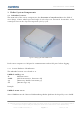
smart microwave sensors GmbH 3 Radar System Components 3.1 Individual sensors The main task of the sensor component is the detection of any obstacles in the field of view. Range, relative radial speed and angle of each object are measured. Its interface to the central processor is the object list reported cycle by cycle. Figure 1: Photograph of the UMRR Sensor Each sensor comprises a CAN port for communication and an SPI port for data logging. 3.1.
smart microwave sensors GmbH 3.1.2 Sensor Software Identification The sensor software is given as follows: Example: Umrrflsh_ID0_RF1208_DSP0436_Rel005_2004-02-18_P_ACCSG_OUV Umrrflsh Software for Flash or RAM Download ID0 Sensor ID in the network RF1108 RF Module Serial Number DSP0366 DSP Module Serial Number Rel005 Software Release P Platform Software ACCSG Parameter Settings for ACC Stop&Go Application OUV Software for Upside Down Mounted Sensor 3.1.
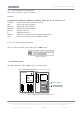
smart microwave sensors GmbH The UMRR consists of a DSP (digital signal processing) board controlling the RF circuit. All interactions with the user are through the DSP board interfaces, mainly CAN (Controller Area Network) interface. The DSP board controls the VCO through an internal SPI (Serial Peripheral Interface). The VCO signal is split into transmit and receive path. The transmit path feeds the TX antenna. The receive path feeds mixers for the receive antennas.
smart microwave sensors GmbH 4 Sensor System Architectures 4.1 Stationary Applications The UMRR sensor family can be used for many stationary applications. Among those are: - Surveillance systems - Moving objects detection - Traffic monitoring - Traffic enforcement - Rail applications etc.
smart microwave sensors GmbH 5 Antenna 5.1 Type 29 This setup is commonly used for long range applications like ACC or similar rear-looking functions. Parameter Type Operational Mode(s) Maximum Range (Truck) Maximum Range (Car) Max. Range (Pedestrian) Azimuth 3dB Limits Elevation 3dB Limits Max. Az. Field of View Antenna Type Housing Type Value 29 FMSK 240m 160m 60m +-6 degree +-4 degree +-20 degree Patch Antenna 5.6(.x) / 5.7 Figure 4: Type 29 antenna single sensor setup.
smart microwave sensors GmbH 6 Cables and Connectors The set of cables and connectors comes prepared with the sensor system to avoid damage due to pinout mismatches. 6.1 Sensor Connector Mounted on the back side of the radar there is a 8 pin male circular connector (waterproof IP67 series 702, manufacturer Binder GmbH, Germany). You must connect a female counterpart (see drawing): Figure 5: Sensor Connector (UMRR Housing 5.6.
smart microwave sensors GmbH Figure 6: Sensor Connector (UMRR Housing 5.7) Figure 7: Female counterpart of sensor connector (rear view) Sensor Version UMRR9.xx: Pin 1 2 3 4 5 6 7 8 UMRR-yyxx Color (New Cables) GND Blue = GND CAN_L CAN_H Yellow = CAN_L Green = CAN_H +8V…+32V Red = +8V…+32V Table 1: Sensor Connector Pinout CONFIDENTIAL AND PROPRIETARY The Information contained in this document shall remain the sole exclusive property of s.m.
smart microwave sensors GmbH 7 Mechanical Interface 7.1 Single Sensor Housing Version 5.6.1 Sensor Housing: Weight: WxHxD: 110mm x 99mm x 30mm 455g (Al body) Vent area, do not cover entirely Figure 8: Housing V5.6(.x) aspects CONFIDENTIAL AND PROPRIETARY The Information contained in this document shall remain the sole exclusive property of s.m.s smart microwave sensors GmbH and shall not be disclosed by the recipient to third parties without prior consent of s.m.
smart microwave sensors GmbH Figure 9: 3D representation of Housing V5.6(.x) CONFIDENTIAL AND PROPRIETARY The Information contained in this document shall remain the sole exclusive property of s.m.s smart microwave sensors GmbH and shall not be disclosed by the recipient to third parties without prior consent of s.m.s smart microwave sensors GmbH in writing.
smart microwave sensors GmbH 7.2 Single Sensor Housing Version 5.7 Sensor Housing: Weight: WxHxD: 110mm x 99mm x 30mm 421g (Al body) Figure 10: Housing V5.7 aspects CONFIDENTIAL AND PROPRIETARY The Information contained in this document shall remain the sole exclusive property of s.m.s smart microwave sensors GmbH and shall not be disclosed by the recipient to third parties without prior consent of s.m.s smart microwave sensors GmbH in writing.
smart microwave sensors GmbH Figure 11: 3D representation of Housing V5.7 7.3 Coverage of the sensor The sensors have a weather proof plastic radome, which is optimized along with the antenna. It is not necessary to protect the sensors by any additional means. Hence, for an optimum detection performance, do not mount the radar behind bumper material or similar covers. The effective range will then be reduced depending on the transmission attenuation of the material.
smart microwave sensors GmbH 8 Co-ordinate System Figure illustrates the co-ordinate system of a radar system . - the data are reported in Cartesian co-ordinates. If sensors are used stand-alone, without the central ecu, they report the targets in a sensor co-ordinate system which is specified similar to the picture given below. - The sensor position respresents the origing then - The sensor pointing direction is equal to the x-axis - The data are reported in polar co-ordinates.